Image stabilizing apparatus for camera module

a technology for stabilizing apparatus and camera modules, which is applied in the field of image stabilizing apparatus for camera modules, can solve the problems of deteriorating image quality, durability problems, and increasing costs, and achieve the effect of effective stabilizing images and reducing the manufacture cost of camera modules

Inactive Publication Date: 2009-12-10
SAMSUNG ELECTRO MECHANICS CO LTD
View PDF5 Cites 56 Cited by
  • Summary
  • Abstract
  • Description
  • Claims
  • Application Information

AI Technical Summary

Benefits of technology

[0012]The present invention has been invented in order to overcome the above-described disadvantages and problems of the conventional image stabilizing apparatuses for camera modules and it is, therefore, an object of the present invention to provide an image stabilizing apparatus for a camera module capable of effectively stabilizing an image of the camera module, implementing miniaturization and slimness of the camera module, and reducing a manufacture cost of the camera module by supplying a two-axial correction structure to perform correction in an X axial direction or an Y axial direction of an automatic focusing unit through a ball holder having upper balls and lower balls.

Problems solved by technology

However, the moving method of the image stabilizing optical lens complicates a redesign in changing an optical design due to driving of a corresponding optical lens, the image sensor moving method needs high driving precision and caused noise due to heat generation, the prism refraction method increases a cost and deteriorates image quality, and the method for entirely leaning the camera module to cope with the shake complicates construction of a product and causes a durability problem.
Particularly, a linear guide method as one of the conventional image stabilizing methods applied to the digital camera reduces a driving performance due to friction and a size of the mobile small cameral module adopting this method is sharply increased.
In order to overcome the above-described disadvantages, an image stabilizing technique using moving balls and slide grooves has been developed, however, because a constraint condition of a structure using the moving balls and the slide grooves is unstable, the moving balls are easily separated due to external impact, and because additional moving balls and slide grooves are applied to each horizontal axial direction changed for image stabilization, a volume in an optical axial direction is increased and the numbers of the moving balls and the corresponding slide grooves are increased, thereby driving up a manufacture cost.

Method used


Image

  • Image stabilizing apparatus for camera module
  • Image stabilizing apparatus for camera module
  • Image stabilizing apparatus for camera module

Examples


Embodiment Construction

[0029]Hereinafter, a preferable embodiment of an image stabilizing apparatus for a camera module in accordance with the present invention will be described in detail with reference to the accompanying drawings.

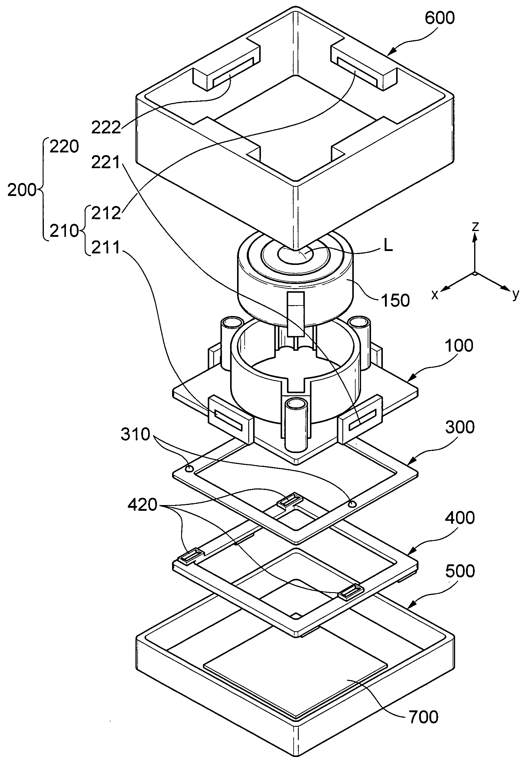
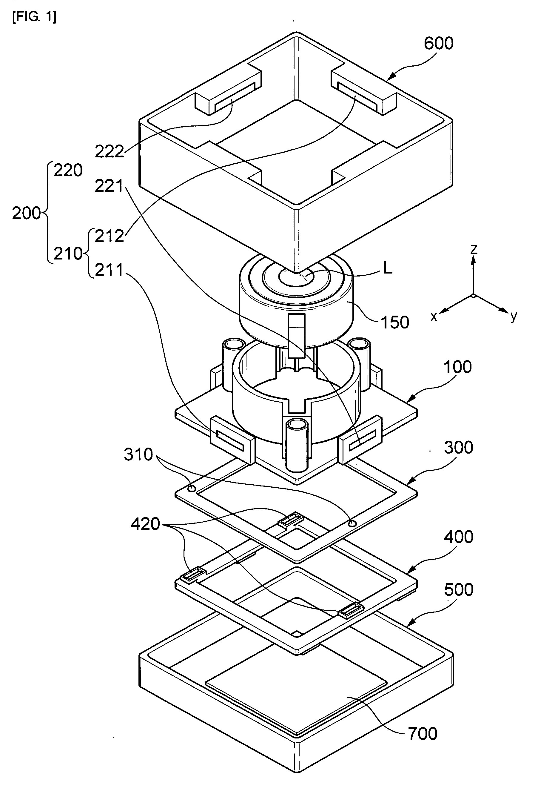
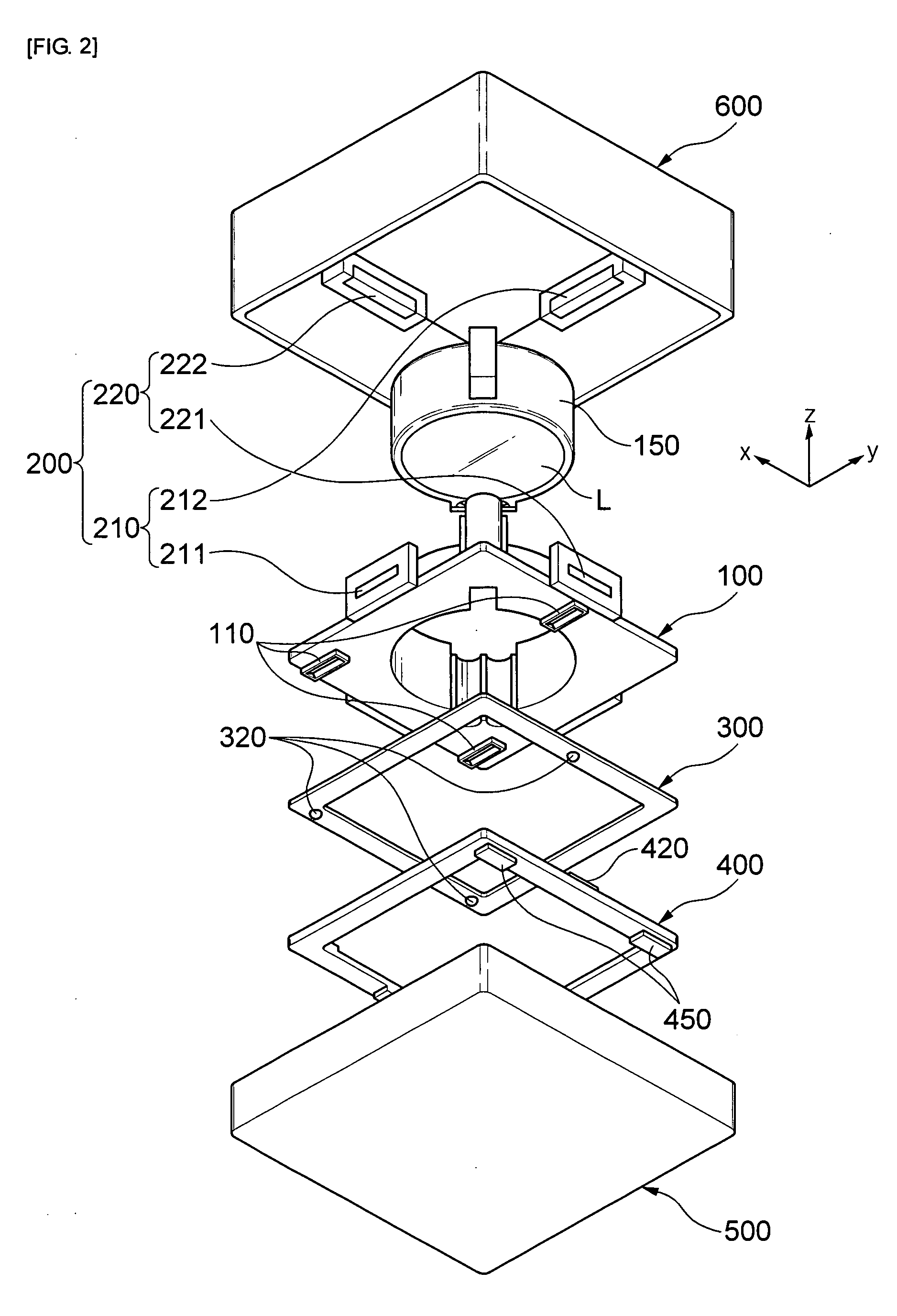
[0030]FIG. 1 is a schematic exploded perspective view illustrating an image stabilizing apparatus for a camera module from a top side in accordance with one embodiment of the present invention and FIG. 2 is a schematic exploded perspective view illustrating the image stabilizing apparatus for the camera module from a bottom side in accordance with the one embodiment of the present invention.

Embodiment of an Image Stabilizing Apparatus for a Camera Module

[0031]As shown in FIG. 1 and FIG. 2, in accordance with one embodiment of the present invention, an image stabilizing apparatus for a camera module includes an automatic focusing unit 100, a driving unit 200, a ball holder 300, a lower guide 400, a lower housing 500, and an upper housing 600.

[0032]The automatic focusing unit 10...


PUM


Abstract

The present invention relates to an image stabilizing apparatus for a camera module capable of effectively stabilizing an image of the camera module, implementing miniaturization and slimness, and reducing a manufacture cost of the camera module by supplying a two-axial correction structure to perform correction in an X axial direction or an Y axial direction of an automatic focusing unit through a ball holder having upper balls and lower balls.To achieve the object, the present invention provides an image stabilizing apparatus for a camera module including; an automatic focusing unit with slide grooves having lengths in an X axial direction or in an Y axial direction perpendicular to an optical axis on a bottom surface; a driving unit for moving the automatic focusing unit in the X axial direction or the Y axial direction; a ball holder installed on the bottom surface of the automatic focusing unit and provided with upper balls slidably coupled to the slide grooves on a top surface and lower balls on a bottom surface; and a lower guide which is installed on the bottom surface of the ball holder and includes slide grooves on a top surface, wherein the slide grooves are slidably coupled with the lower balls of the ball holder and have lengths in the Y axial direction or the X axial direction perpendicular to a longitudinal direction of the slide grooves of the automatic focusing unit.

Description

CROSS-REFERENCE TO RELATED APPLICATIONS[0001]This application claims the benefit of Korean Patent Application No. 10-2008-0053701 filed with the Korea Intellectual Property Office on Jun. 9, 2008, the disclosure of which is incorporated herein by reference.BACKGROUND OF THE INVENTION[0002]1. Field of the Invention[0003]The present invention relates to an image stabilizing apparatus for a camera module; and, more particularly, to an image stabilizing apparatus for a camera module capable of effectively stabilizing an image of the camera module, implementing miniaturization and slimness of the camera module and reducing a manufacture cost of the camera module by supplying a two-axial correction structure to perform correction in an X axial direction or an Y axial direction of an automatic focusing unit through a ball holder having upper balls and lower balls.[0004]2. Description of the Related Art[0005]Generally, an image stabilizing apparatus has been used to prevent deterioration of...

Claims


Application Information

Patent Timeline
Patent Type & Authority Applications(United States)
IPC IPC(8): G02B27/64
CPCG02B27/646H04N5/23287H04N5/2257H04N5/2254H04N23/50H04N23/57H04N23/687H04N23/55
Inventor LIM, SOO CHEOLPARK, NO CHEOLSONG, MYEONG GYUMOON, JAE HOJEONG, HO SEOPPARK, JAE HYUK
Owner SAMSUNG ELECTRO MECHANICS CO LTD
Why Eureka
Try Eureka