LED lens mounting device

a technology for mounting devices and led lenses, which is applied in the direction of fixed installation, lighting and heating equipment, lighting support devices, etc., can solve the problem of relatively incorrect positioning of the lens

Inactive Publication Date: 2009-12-10
HELLA KG HUECK & CO
View PDF2 Cites 44 Cited by
  • Summary
  • Abstract
  • Description
  • Claims
  • Application Information

AI Technical Summary

Problems solved by technology

This gap and variability of the frame parts that define the gap frequently cause the position of the lens to be relatively incorrect.

Method used


Image

  • LED lens mounting device
  • LED lens mounting device
  • LED lens mounting device

Examples


Embodiment Construction

[0020]The following description of the preferred embodiment(s) is merely exemplary in nature and is in no way intended to limit the invention, its application, or uses.

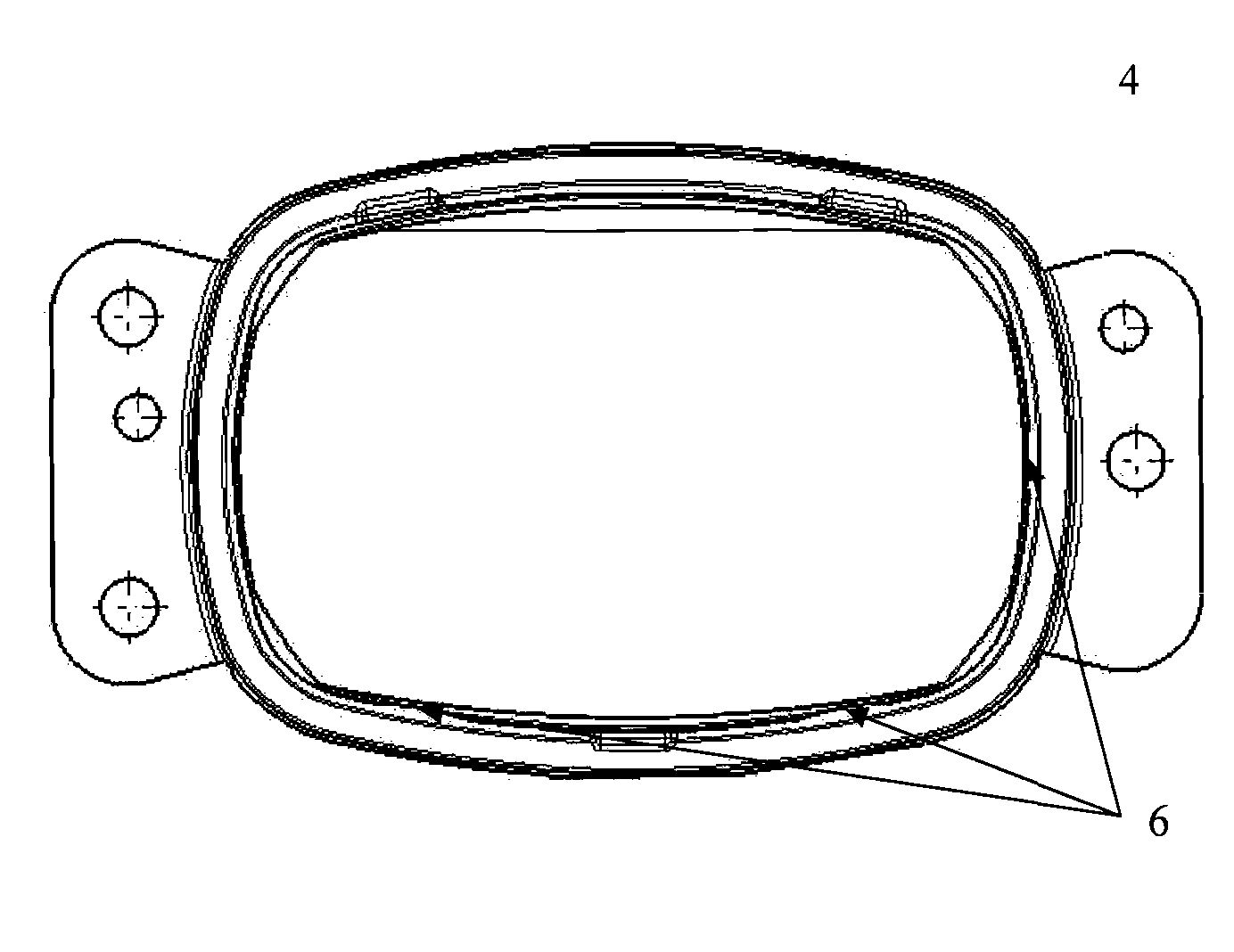
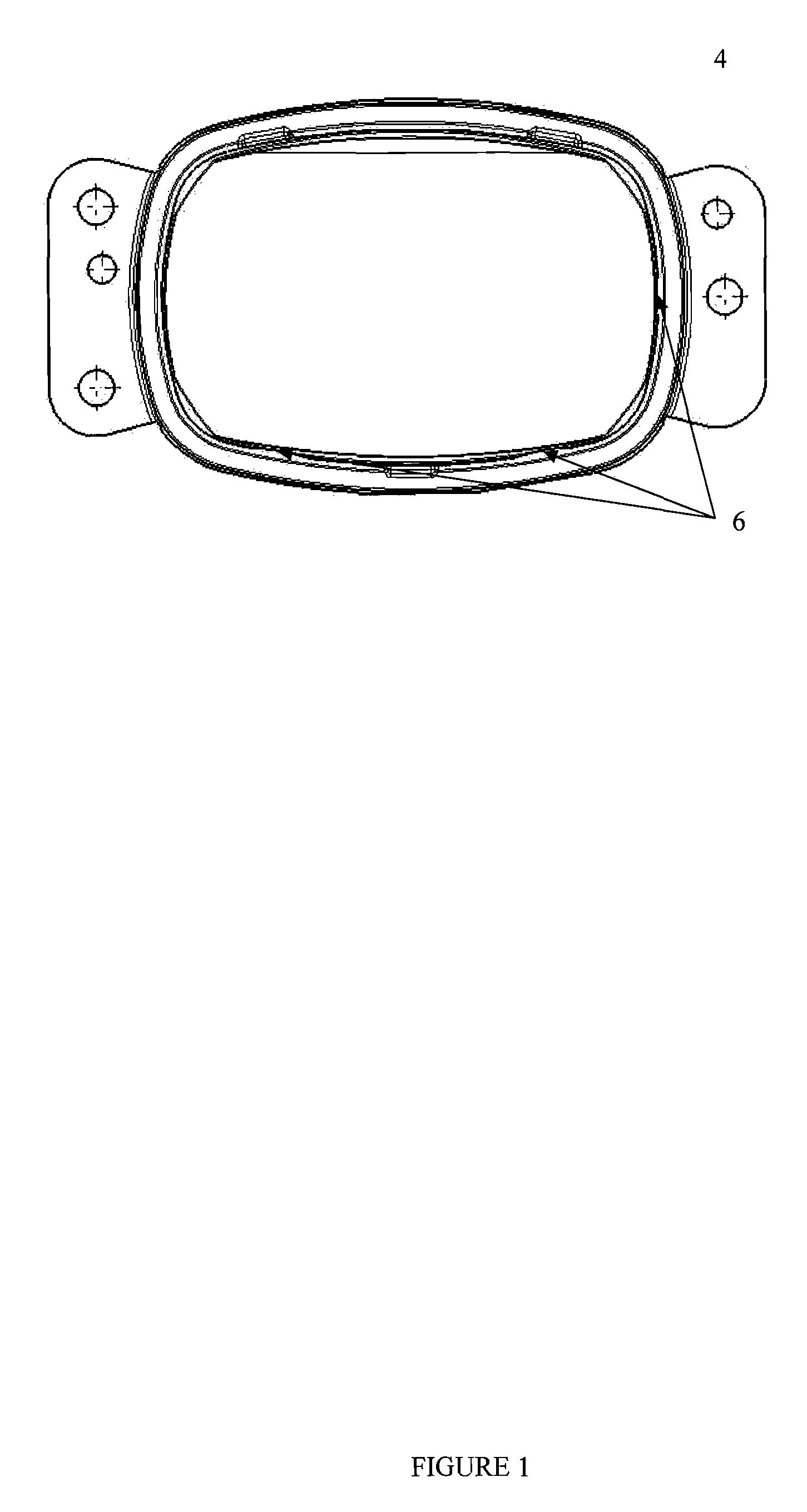
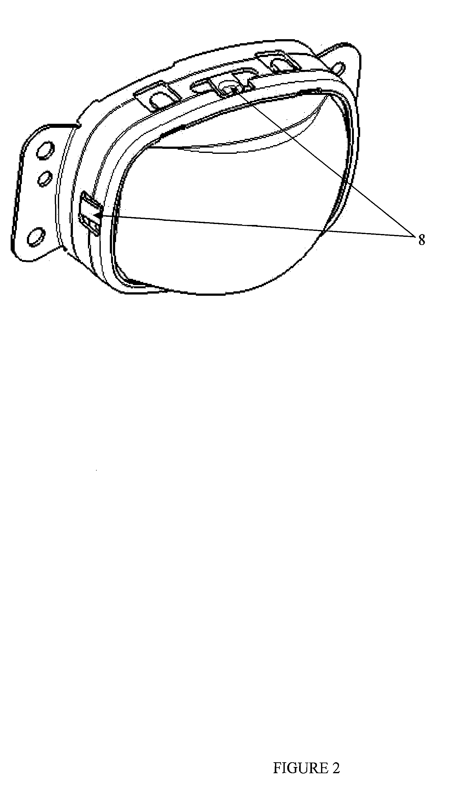
[0021]Referring now to the drawings wherein like reference numbers indicate like elements, FIG. 1 is a front view of a headlight wherein lens 2 is mounted on frame 4 at register or datum points 6. The lens is held in place by feather or spring latches 8, seen in FIG. 2

[0022]The LED will be mounted behind the frame. FIG. 3 depicts the LED unit 10. The LED unit 10 is comprised of a heat sink 12, the LED board 14 and LED board mounting screws 16. In the present invention, the heat sink 12 includes screw holes 20. In the center of the LED board 14 is the LED 18. Multiple LEDs or multiple LED boards may be mounted on the heat sink. Such groups may be adjusted to each other and may add up to a complete beam pattern.

[0023]The heat sink / LED module 10 is placed on a heat sink / LED carrier by three screws mounted through screw h...


PUM


Abstract

A headlight for a vehicle has a lens, a mounting frame, an LED on an LED board. The LED board is mounted on a heat sink. The heat sink has a first adjustment slot and a second adjustment slot. Each of the slots is dimensioned and disposed to closely cooperate with an eccenter adjustment device mounted on one of the LED module or an LED module carrier, said eccenters being adjustable on a fulcrum such that adjustment of one of the eccenters adjusts one of a first position or a second position of the LED module within a plane normal to an optical axis of a lens mounted in a fixed position relative to the LED module carrier.

Description

CROSS-REFERENCE TO RELATED APPLICATIONS[0001]This application claims priority to U.S. Provisional Application 61 / 058,787 filed Jun. 4, 2008.BACKGROUND OF THE INVENTION[0002]1. Field of the Invention[0003]The present invention is an adjustable mount for an LED used in lights such as automobile headlights.[0004]2. Related Art[0005]LED lens modules have a short focal length. This requires a very accurate positioning of the LEDs relative to the optical axis of the lens to fulfill the optical requirements. Because of the relatively large tolerances of the parts included in the system, adjustments of the LED are often needed. To minimize the adjustment range, the lens should be positioned relative to the lens as accurately as possible.[0006]Current positioning of the lens in the lens frame system works with static attachment points. There is a gap between lens and frame that is incorporated into the system to allow for tolerances. This gap and variability of the frame parts that define th...

Claims


Application Information

Patent Timeline
Patent Type & Authority Applications(United States)
IPC IPC(8): F21V29/00
CPCF21S48/1145F21S48/1208F21Y2101/02F21V17/12F21W2101/10F21V17/02F21Y2115/10F21S41/295F21S41/151F21S45/48F21W2102/00
Inventor BORGSCHULTE, HUBERTSPORK, HEINZ-UWESUDAHL, JORG
Owner HELLA KG HUECK & CO
Why Eureka
Try Eureka