Asynchronous ping-pong counter and therof method

a counter and asynchronous technology, applied in the field of design of counters, can solve the problems of almost impossible to meet the setup and hold timing requirements of each flip-flop by using any synchronous counter in existing technologies

Active Publication Date: 2009-12-10
REALTEK SEMICON CORP
View PDF5 Cites 9 Cited by
  • Summary
  • Abstract
  • Description
  • Claims
  • Application Information

AI Technical Summary

Benefits of technology

[0006]In one embodiment, an asynchronous ping-pong counter comprises an edge detector, a dual asynchronous counter, and a finite state machine. The edge detector receives a first input clock and a second input clock, and generates a pulse signal to indicate the arrival of a rising edge of the second input clock. The rising edges of the first input clock are arranged into different time slots on the basis of the pulse signal generated by the edge detector. The dual asynchronous counter receives a binary select signal from the finite state machine and the first input clock, and generates a counter value that is the number of the rising edges in each time slot. The dual asynchronous counter includes a first asynchronous counter and a second asynchronous counter. When the first asynchronous counter is receiving the rising edges of the first input clock in the current time slot, the second asynchronous counter is calculating the number of the rising edges in the previous time slot and generating the counter value and vice versa. The choice of which asynchronous counter is selected depends on the binary value of the select signal. The finite state machine receives the pulse signal and the first input clock, and generate the select signal to indicate that the rising edges of the first input clock is coupled to either the first asynchronous counter or the second asynchronous counter. The select signal also indicates which asynchronous counter outputs the counter value in the previous time slot.
[0006]In one embodiment, an asynchronous ping-pong counter comprises an edge detector, a dual asynchronous counter, and a finite state machine. The edge detector receives a first input clock and a second input clock, and generates a pulse signal to indicate the arrival of a rising edge of the second input clock. The rising edges of the first input clock are arranged into different time slots on the basis of the pulse signal generated by the edge detector. The dual asynchronous counter receives a binary select signal from the finite state machine and the first input clock, and generates a counter value that is the number of the rising edges in each time slot. The dual asynchronous counter includes a first asynchronous counter and a second asynchronous counter. When the first asynchronous counter is receiving the rising edges of the first input clock in the current time slot, the second asynchronous counter is calculating the number of the rising edges in the previous time slot and generating the counter value and vice versa. The choice of which asynchronous counter is selected depends on the binary value of the select signal. The finite state machine receives the pulse signal and the first input clock, and generate the select signal to indicate that the rising edges of the first input clock is coupled to either the first asynchronous counter or the second asynchronous counter. The select signal also indicates which asynchronous counter outputs the counter value in the previous time slot.

Problems solved by technology

However, if the fast clock runs at a very high speed, e.g. 5 GHz, and the slow clock runs at an extremely slow speed, e.g. 10 MHz, it is almost impossible to meet both the setup and hold timing requirements of each flip-flop by using any synchronous counter in existing technologies.

Method used


Image

  • Asynchronous ping-pong counter and therof method
  • Asynchronous ping-pong counter and therof method
  • Asynchronous ping-pong counter and therof method

Examples


Embodiment Construction

[0014]In the present disclosure, numerous specific details are provided, such as examples of electrical circuits, components, and methods, to provide a thorough understanding of embodiments of the invention. Persons of ordinary skill in the art will recognize, however, that the invention can be practiced without one or more of the specific details. In other instances, well-known details are not shown or described to avoid obscuring aspects of the invention.

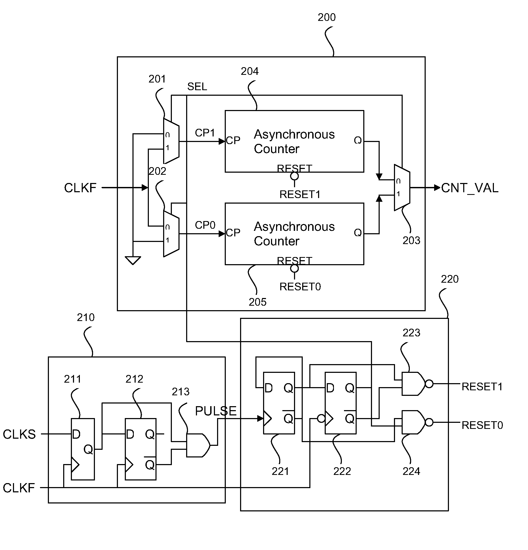
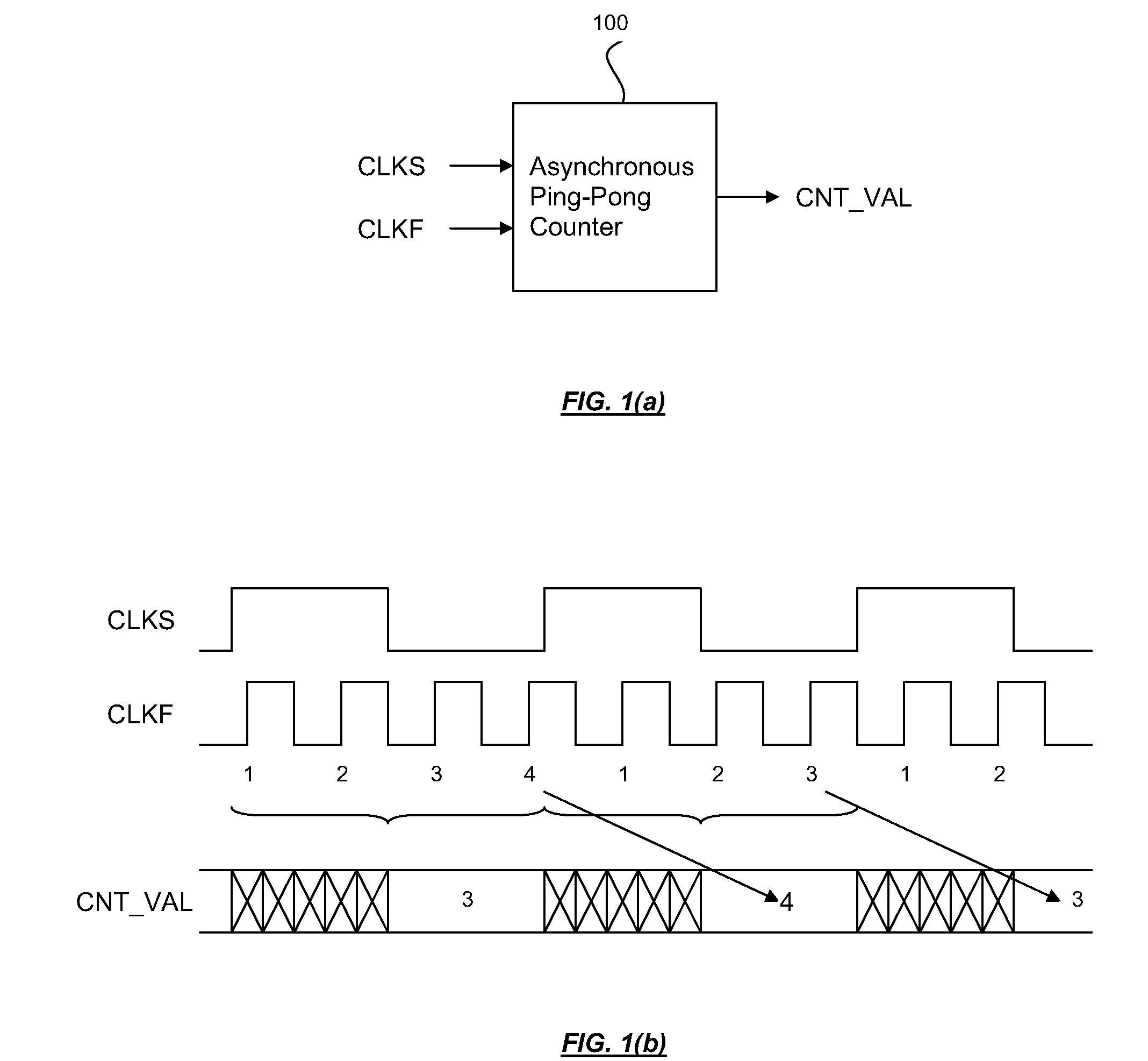
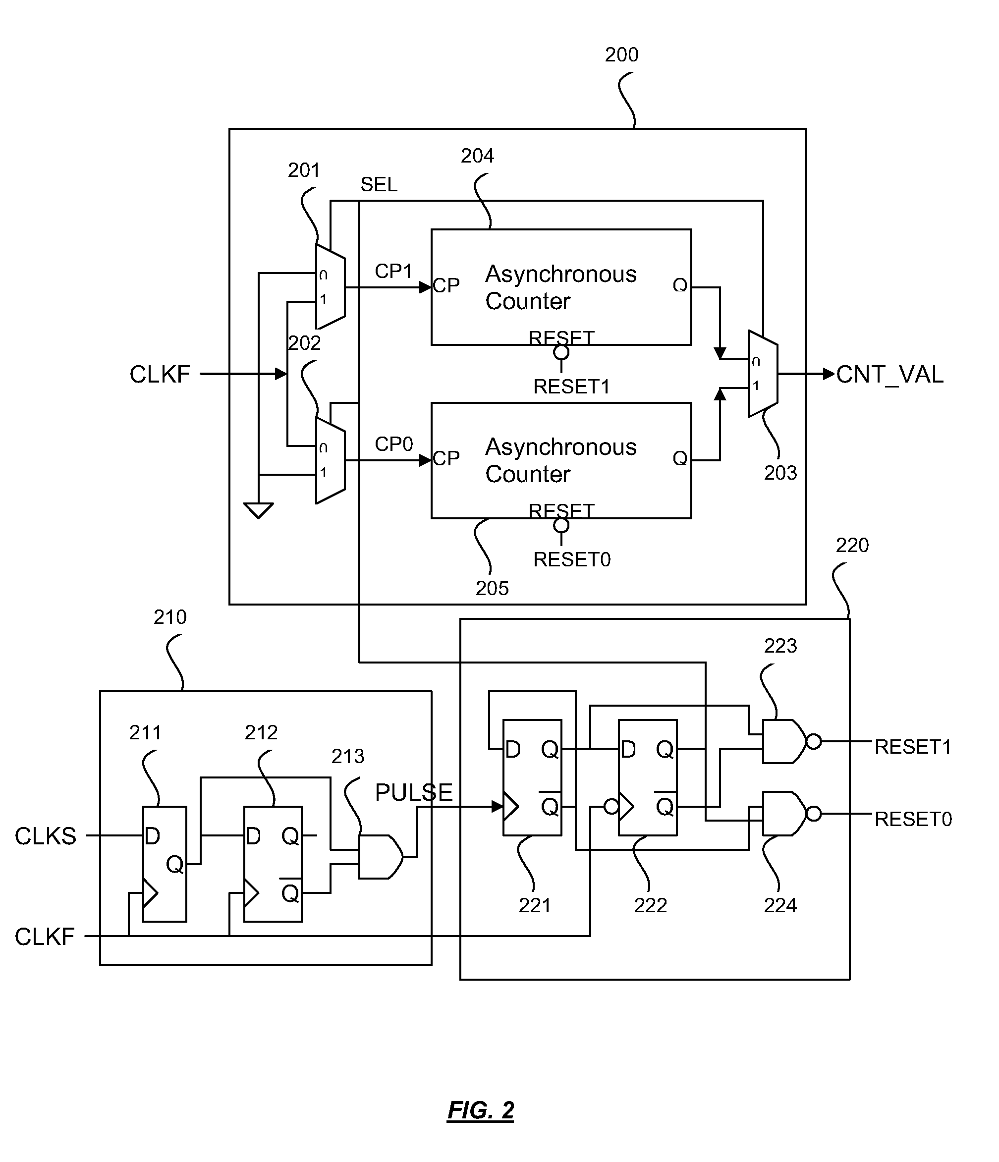
[0015]FIG. 1(a) shows a proposed asynchronous ping-ping counter in accordance with an embodiment of the present invention. In the example of FIG. 1(a), the asynchronous ping-pong counter receives a first input clock (CLKF in FIG. 1(a)), a second input clock (CLKS in FIG. 1(a)), and generates a digital output (CNT_VAL in FIG. 1(a)) that is the number of rising edges of the first input clock between two neighboring rising edges of the second input clock. Typical input and output waveforms are shown in the timing diagram of FIG. 1(b)...


PUM


Abstract

An asynchronous ping-pong counter is disclosed. The asynchronous ping-pong counter comprises a first asynchronous counter, a second synchronous counter, and a controller, the asynchronous ping-pong counter operates between a first state and a second state. In the first state, the first asynchronous counter counts a first number of clock edges of a fast clock signal, and the second asynchronous counter holds a first counter output value. In the second state, the second asynchronous counter counts a second number of clock edges of the fast clock signal, and the first asynchronous counter holds a second counter output value. The controller determines a state transition based on a sampling of a slow clock signal by the fast clock signal.

Description

CROSS REFERENCE TO RELATED APPLICATIONS[0001]This application claims the benefit of U.S. Provisional Application No. 61 / 059,229, filed on Jun. 5, 2008 and entitled “ASYNCHRONOUS PING-PONG COUNTER”, the contents of which are incorporated herein by reference.BACKGROUND OF THE INVENTION[0002]1. Field of the Invention[0003]The present invention relates generally to the design of a counter. In particular, it relates to the design of an asynchronous ping-pong counter.[0004]2. Description of the Background Art[0005]A counter is defined here as a building block that receives a fast clock and a slow clock, and generate an output value. A rising edge is defined as the transition of a digital signal from low to high. The output value represents the number of rising edges of the fast clock that exists between two neighboring rising edges of the slow clock. A synchronous counter clocked by the fast clock can be used to over-sample the slow clock to determine the number of rising edges by inspect...

Claims


Application Information

Patent Timeline
Patent Type & Authority Applications(United States)
IPC IPC(8): H03K21/38
CPCH03K23/58H03K21/38
Inventor HSIEH, HONG-YEAN
Owner REALTEK SEMICON CORP
Why Eureka
Try Eureka