Ventilation controlling apparatus and method for controlling ventilation in motor vehicles

Active Publication Date: 2009-12-10
MAHLE INT GMBH
View PDF16 Cites 18 Cited by
  • Summary
  • Abstract
  • Description
  • Claims
  • Application Information

AI Technical Summary

Benefits of technology

[0017]In an alternative embodiment of the invention, the second shaft or a part of it is arranged coaxially inside a hollow section of the first one or vice versa. The mechanical link comprises a loaded spring eng

Problems solved by technology

When air humidity is high as it tends to be the case the more passengers are inside the side windows are prone to fog up.
The disadvantage is its need for space in order to package the two coils as well as the challenge to se

Method used


Image

  • Ventilation controlling apparatus and method for controlling ventilation in motor vehicles
  • Ventilation controlling apparatus and method for controlling ventilation in motor vehicles
  • Ventilation controlling apparatus and method for controlling ventilation in motor vehicles

Examples


Embodiment Construction

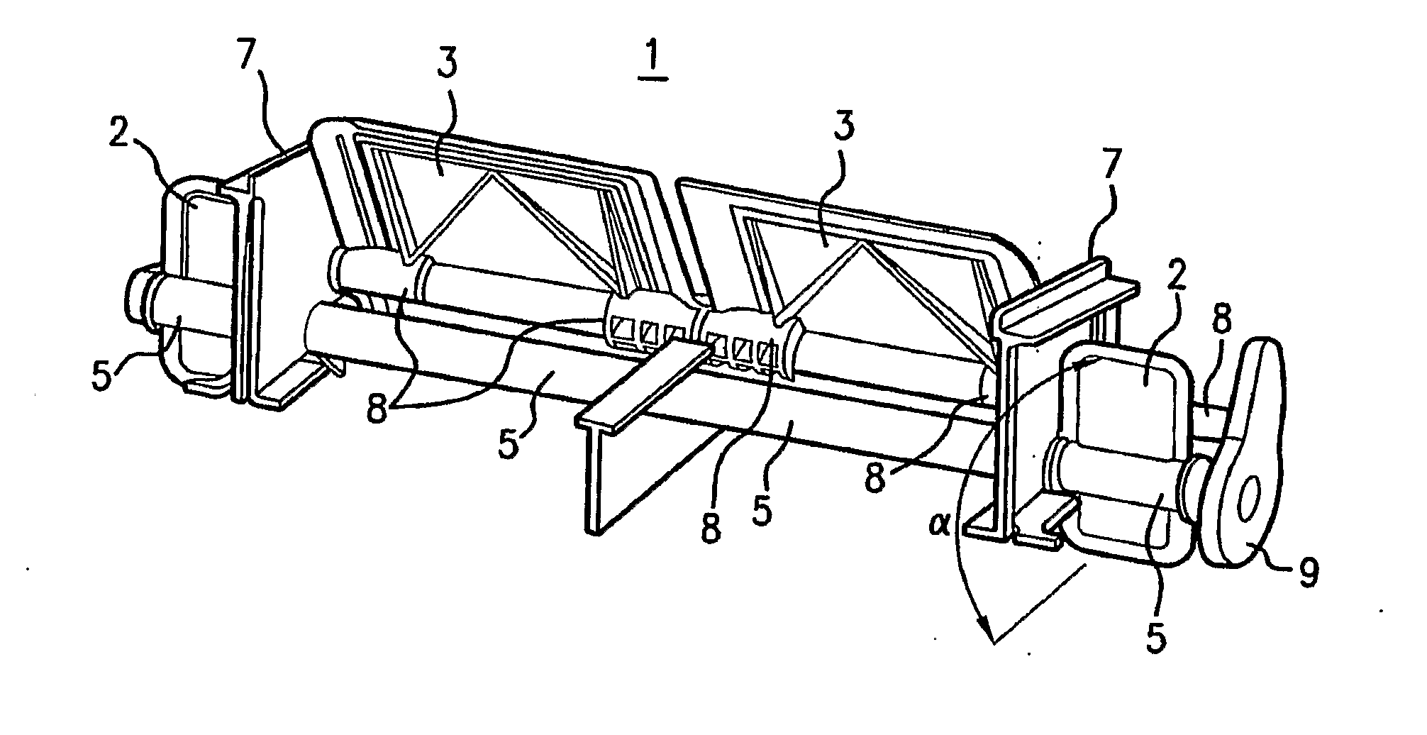
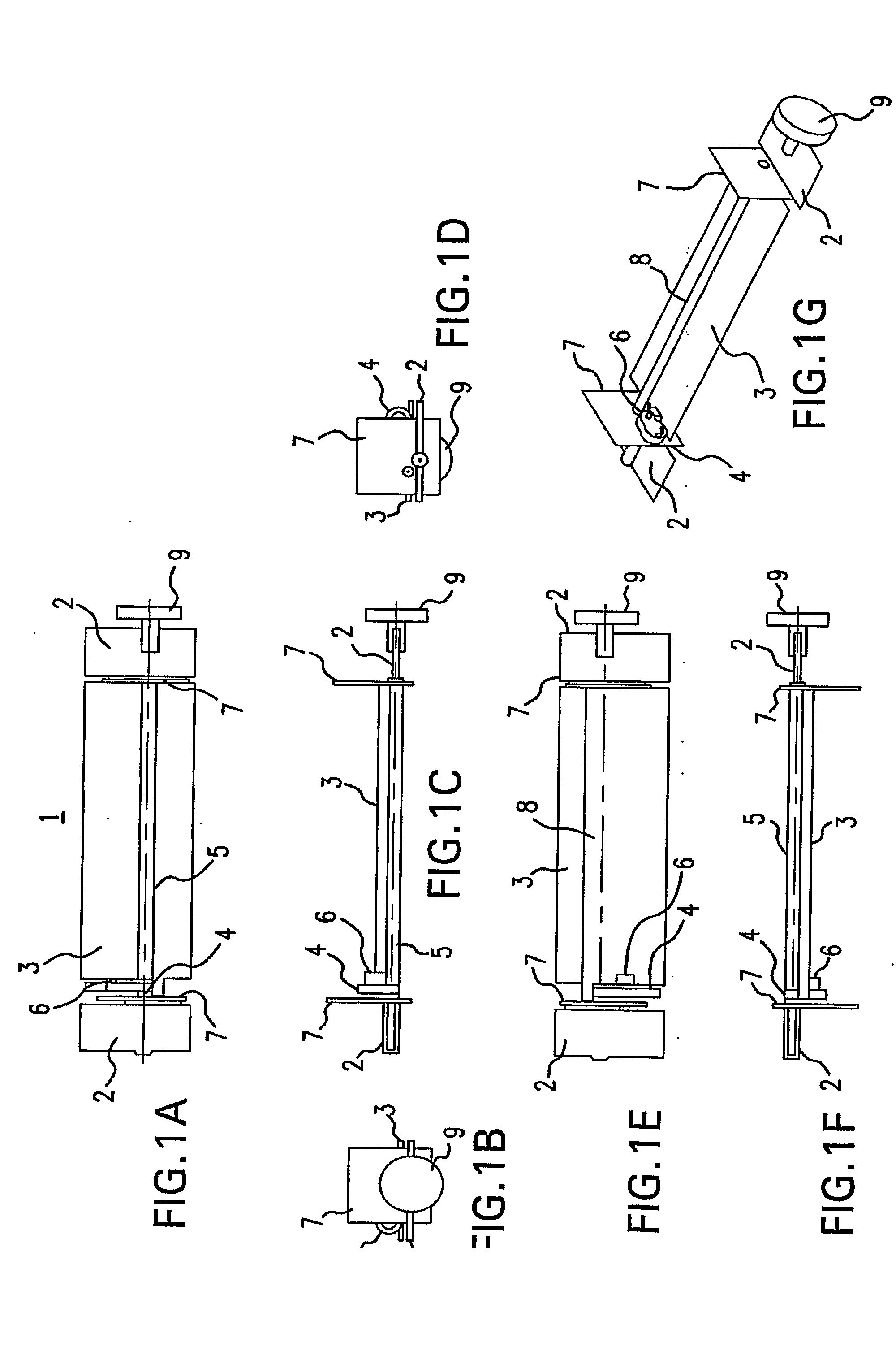
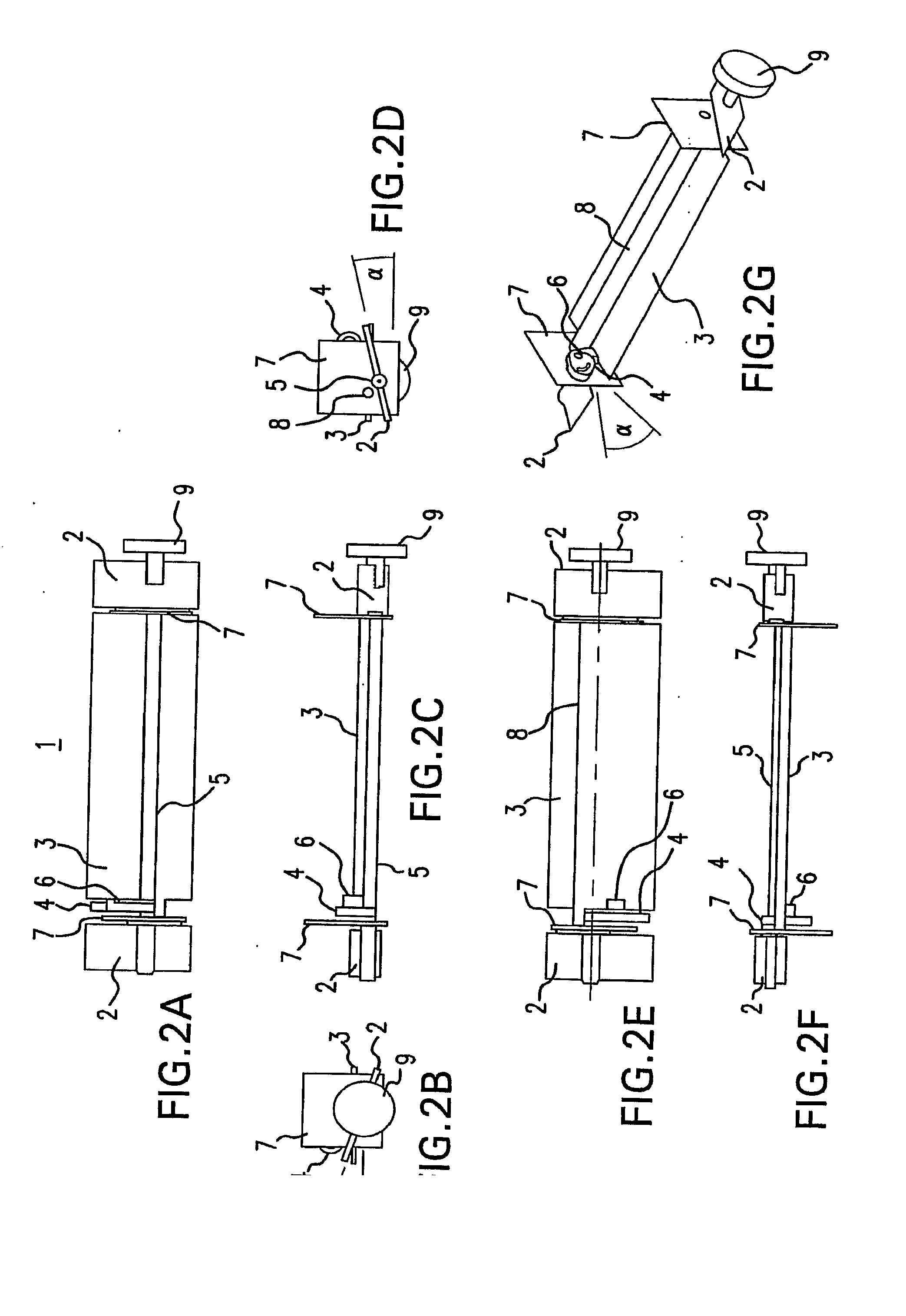
[0055]Referring now to the figures of the drawings in detail and first, particularly, to FIG. 1A thereof, there is shown the bottom view of a first embodiment of a ventilation controlling apparatus 1 according to the invention with two first doors 2, one second door 3 and a cam 4 attached to the first shaft 5 to which the first doors 2 are also attached. A pin 6 is attached to the second door 3 and engaged in the cam 4. The air passages (not shown in their entirety) sealable by the doors 2, 3 are separated by partition walls 7 where a second shaft 8 (only shown in the top view in FIG. 1E and the perspective view in FIG. 1G) molded in one piece with the second door 3 has its bearings.

[0056]The first shaft 5 is turned by means of the drive element 9 to an angle which causes the first doors 2 attached to that first shaft 5 to take a so called door stop position, meaning they are aligned horizontally where they seal tight their respective air passages, which are designed accordingly. Th...


PUM


Abstract

A ventilation controlling apparatus for feeding windshield defrost outlets and side window demist outlets in motor vehicles with one or more air passages and respective doors for each outlet. The apparatus supports a mode in which the demist door opens up to a predefined angle without the defrost door opening, too, with the predefined angle depending on the design of a cam attached to the demist door and a pin engaged with that cam and attached to the defrost door.

Description

BACKGROUND OF THE INVENTION[0001]The present invention relates to a ventilation controlling apparatus and a method for controlling ventilation, particularly for feeding defrost and side window demist outlets in motor vehicles.[0002]In motor vehicles at moderate outside temperatures (up to 25° C.) passengers usually prefer using the bi-level ventilation mode of a heating, ventilation and air conditioning (HVAC) unit. In this mode vent and floor outlets are at least partially open. When air humidity is high as it tends to be the case the more passengers are inside the side windows are prone to fog up. To keep passengers comfortable in this situation the side windows demist outlets have to be open while the defrost outlets remain closed. Otherwise there could emerge a fogged up spot on the outside of the windshield.[0003]There are different approaches known for solving this problem. One is the usage of a film door inside the ventilation controlling apparatus as in US 2002 / 0197951 A1. A...

Claims


Application Information

Patent Timeline
IPC IPC(8): B60S1/54
CPCB60H1/00671B60H2001/00707B60H1/00857
Inventor LANGE, MICHAELSCHLINKE, GUNNARRAPPEL, THOMAS
Owner MAHLE INT GMBH
Why Eureka
Try Eureka