
Elastic composite having cross-directional elasticity and a system and method for making the elastic composite

Active Publication Date: 2009-12-10
DSG TECH HLDG
View PDF65 Cites 16 Cited by
  • Summary
  • Abstract
  • Description
  • Claims
  • Application Information

AI Technical Summary

Benefits of technology

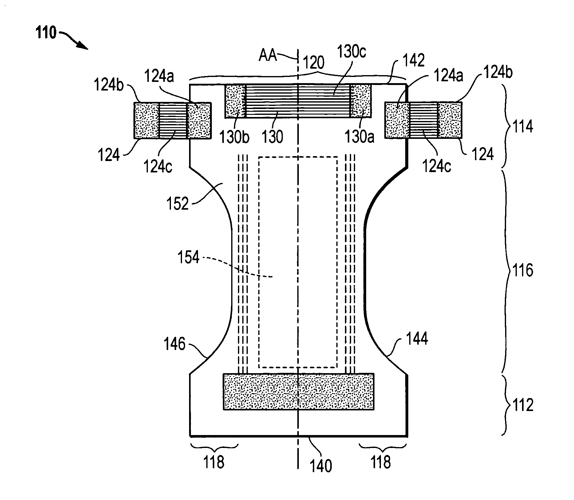
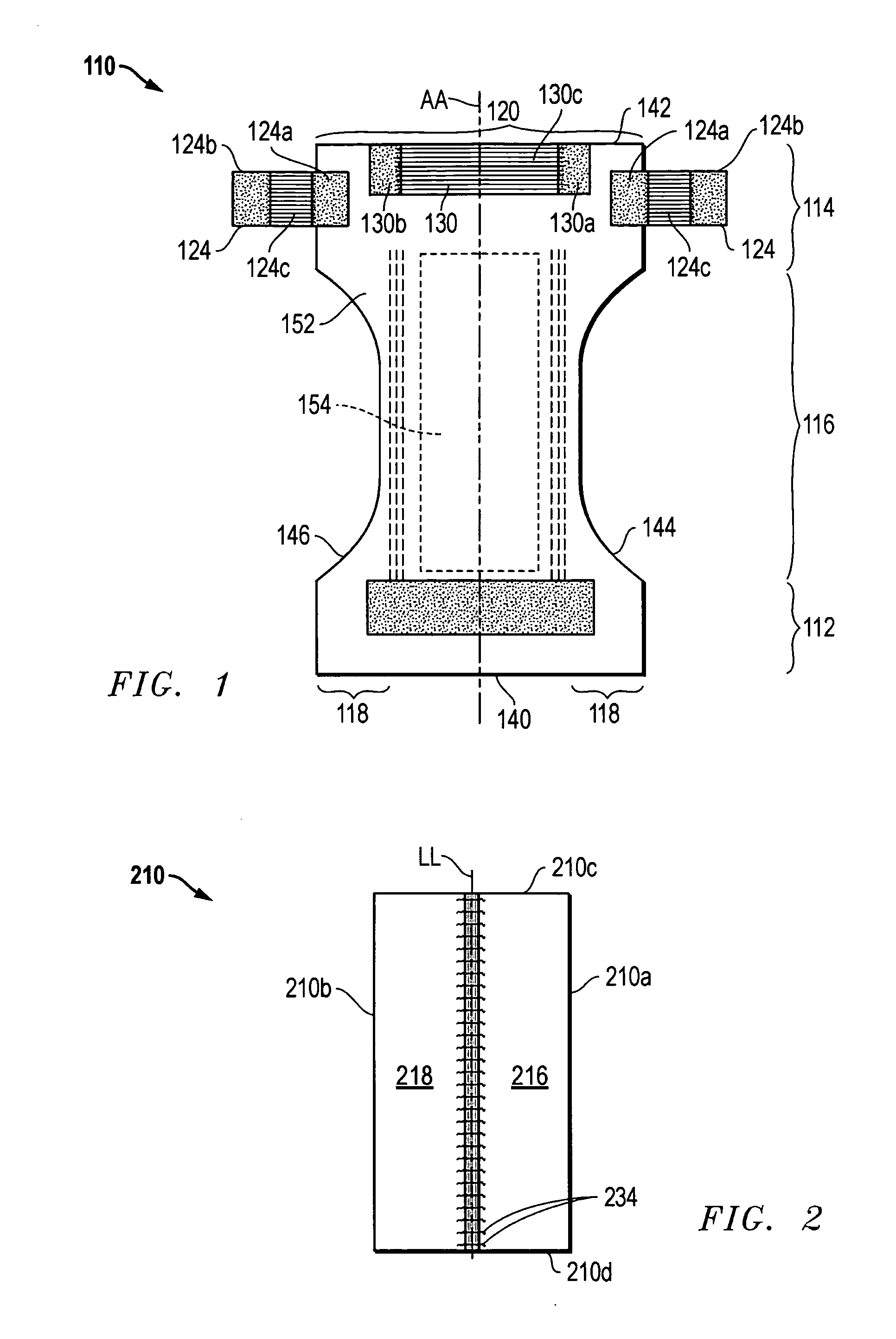
[0129]The use of the inventive elastic composite to form a combined waist and side panel provides certain important advantages over systems utilizing separate elastic materials as the side panel and waist elastic. Firstly, the elastic elements that form the elasticizing function of the waist panel and the side panels are the same, and as such, there is a continual connection of elastic material from one side panel to the opposite side panel as discussed above. As a result, any lateral force applied to the side panels is carried through and directly exerted around the waist of the wearer. This achieves added comfort for the wearer, and helps maintain the article in the correct position about the wearer. Moreover, the improve fit of the article about the wearer along with the reduction of attachments and adhered areas, improves the water-tight seal between the body of the wearer and the article.

Problems solved by technology

The design and construction of the elastic composite can also represent a significant portion of the cost of manufacturing the garment.
Attaining these benefits and advantages presents, however, unique technical challenges.

Method used


Image

  • Elastic composite having cross-directional elasticity and a system and method for making the elastic composite
  • Elastic composite having cross-directional elasticity and a system and method for making the elastic composite
  • Elastic composite having cross-directional elasticity and a system and method for making the elastic composite

Examples


example 1

[0091]In one embodiment of the invention, the width of open elastic region may be approximated as follows:

[0092]Given, conveyor width, W=100 mm;

[0093]distance, d, from upper surface of upper conveyor to lower surface of lower conveyor=40 mm;

[0094]extension applied to continuous elastic strand=4×;

[0095]full extension of elastics=5×.

Widthofopenelasticregion(fullyextended)=5×((100mm+100mm+(40mm×2)) / 4)=350mmWidthofopenelasticregion(relaxed)=(100mm+100mm+(40mm×2)) / 4=70mm

example 2

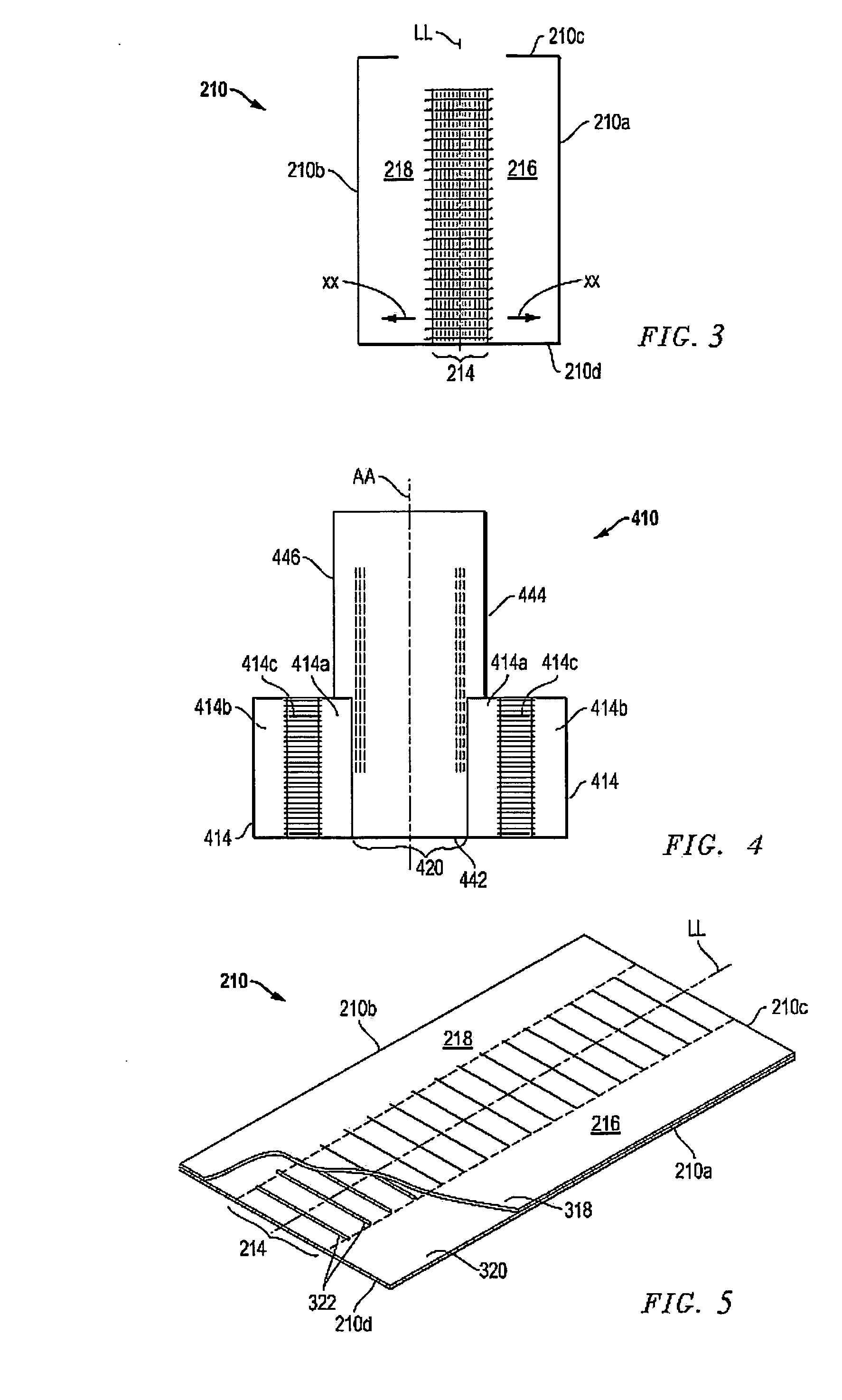
[0096]In a more preferred embodiment, the width of the open elastic region is increased by reducing the extension applied to the elastic strand as it is applied to the nonwoven carrier web. The circumference of the conveyor assembly is also increased by increasing the separation of the upper and lower conveyors. In some suitable systems, one of the conveyor platforms is simply moved further from the other platform. It should also be noted that one of the conveyors is not required to move a sheet of material, but only the elastic wrapped about it. This allows for use of conveyors different from the generally flat platforms or belts commonly used to support a sheet of nonwoven.

[0097]Given, conveyor width, W=100 mm,

[0098]distance, d, from upper surface of upper conveyor to lower surface of lower conveyor=100 mm,

[0099]extension applied to elastics=1.5×,

[0100]full extension of elastics=5×.

Openelasticregion(fullyextended)=5×((100mm+100mm+(100mm×2)) / 1.5)=1333mmOpenelasticregion(relaxed)=(1...


PUM

PropertyMeasurementUnit
Widthaaaaaaaaaa
Elasticityaaaaaaaaaa

Abstract

A method of making an elastic composite entails conveying a first sheet on a conveyor, and wrapping a section of elastic about the first sheet and the conveyor, thereby applying elastics cross directionally across the sheet. A second sheet is then applied onto the first sheet thereby creating a subcomposite including the two sheets and elastics sandwiched therebetween, wherein two elastics extend outward from one side of the subcomposite, about the conveyor, and return into an opposite side of the subcomposite. The subcomposite is cut through the first and second sheets and the elastics, thereby separating the subcomposite into a first carrier and a second carrier, each carrier including a material layer, whereby spaced apart elastics extend from the first carrier to the second carrier, the first and second carriers defining an exposed elastic region therebetween formed by the elastics.

Description

BACKGROUND OF THE INVENTION[0001]The present application claims the benefit of the filing date of U.S. Provisional Application Ser. No. 61 / 124,697 filed on Apr. 18, 2008 (now pending) (which is hereby incorporated by reference for all purposes and made a part of the present disclosure).[0002]The present invention relates generally to elastic composites. More particularly, the present invention relates to an elastic composite that can be used in the manufacture of a garment, other textile or fabric structures, similar material structures, and the like, but more particularly, disposable absorbent articles and garments. The elastic composite of the present invention is well suited in providing an elastic component that can be employed in one or more areas of the disposable absorbent article. The present invention also relates to a system and method of making the elastic. The elastic composite and the system and method for making the elastic composite are particularly suited for use wit...

Claims


Application Information

Patent Timeline
IPC IPC(8): A61F13/51D04H13/00B32B37/02
CPCA61F13/15593A61F13/49011A61F13/49012A61F13/49014Y10T428/24752Y10T156/1066Y10T156/1082Y10T156/1052A61F13/15674Y10T442/602Y10T156/10Y10T156/1044Y10T156/1084A61F13/15747B32B37/12B32B37/142B32B37/18B32B38/00B32B2307/51B32B2307/726B32B2555/02
Inventor TSANG, PATRICK KING YUSMID, ANNEWRIGHT, ANDREW C.VARONA, EUGENIO G.
Owner DSG TECH HLDG
Learn More