Method and apparatus for mounting conductive balls

a technology of conductive balls and mounting surfaces, which is applied in the direction of soldering apparatus, manufacturing tools, non-printed masks, etc., can solve the problems of increasing the probability of problems occurring for conductive balls disposed on the substrate, reducing the performance of balls as electrodes, and shortening the life of moving conductive balls over the surface of masks, etc., to achieve easy correction of surface easy to correct the profile irregularities of masks, and the effect o

Active Publication Date: 2009-12-17
ATHLETE FA KK
View PDF7 Cites 7 Cited by
  • Summary
  • Abstract
  • Description
  • Claims
  • Application Information

AI Technical Summary

Benefits of technology

[0008]It is a first object of the present invention to provide a method and apparatus that can highly reliably fill a plurality of apertures in a mask with conductive balls and can highly reliably arrange or mount conductive balls at predetermined positions on a substrate. It is another object of the present invention to provide a method and apparatus that can reduce a rate of discarded for conductive balls and can economically mount conductive balls at predetermined positions on a substrate.

Problems solved by technology

However, if the number of conductive balls is large relative to the number of apertures, time (life time) of moving the conductive balls over the surface of the mask becomes long.
During the time, due to a number of factors, such as contact with the atmosphere, contact between balls, contact between the balls and the mask, friction and contact between the balls and the squeegee, abrasion and deformation are caused for the surfaces of the balls, which reduce the performance of the balls as electrodes.
Accordingly, if a large number of conductive balls are moved in an attempt to reduce the number of unfilled apertures, or to reduce arrangement errors or mounting errors for a substrate (work) due to unfilled apertures, there is an increase in the probability of problems occurring for the conductive balls disposed on the substrate.
In addition, when a method that moves a large number of balls is used, since it is necessary to discard a large number of conductive balls that have not been disposed, there is an increased rate of loss for the conductive balls that is not preferable from a cost perspective.
When the conductive balls are moved in the same direction by the squeegee, due to the squeegee conditions, the mask conditions, and the like, variations in density of the conductive balls are likely to occur in the longitudinal direction of the squeegee, which can lead to fail of filling of apertures and fail of placing of balls.
When the amount moved by the conductive balls is increased in an attempt to improve the yield, this results in an increased loss of balls in the same way as described above.
However, since the number of particles inserted into the apertures during one time of the movement of the squeegee falls when the times of the back and forth movement are increased, the damage to the particles due to such movement proceeds.

Method used


Image

  • Method and apparatus for mounting conductive balls
  • Method and apparatus for mounting conductive balls
  • Method and apparatus for mounting conductive balls

Examples


Embodiment Construction

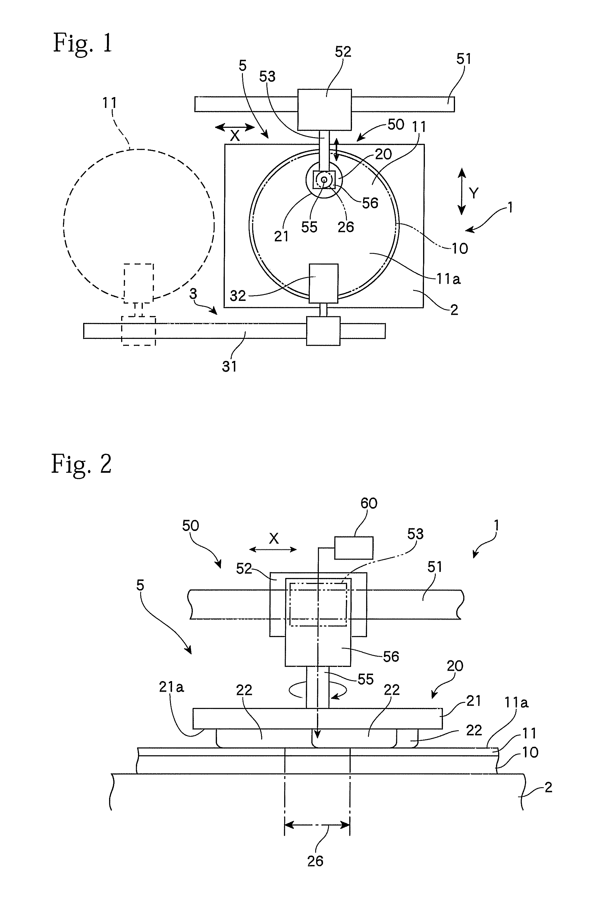
[0038]FIG. 1 shows the general arrangement of a mounting apparatus of one example the present invention. This mounting apparatus 1 is called a ball mounter and disposes conductive balls at predetermined positions on a semiconductor substrate (wafer or work-piece) 10. Almost present wafers 10 are around eight inches or twelve inches in diameter. The conductive balls mounted on the substrate 10 are refined so that the diameter is 1 mm or below. The mounting of balls with a diameter of around 10 to 500 μm is being investigated, with present demand being for the mounting of balls with a diameter of around 30 to 300 μm. Here, “conductive balls” includes solder balls, metal balls made of gold, silver, or the like, and also ceramic balls or plastic balls that have been subjected to a process such as plating with a conductive material.

[0039]The ball mounter 1 includes a table 2 for setting the substrate 10 in a horizontal state where warping is corrected by a method such as attachment by su...


PUM

PropertyMeasurementUnit
diameteraaaaaaaaaa
diameteraaaaaaaaaa
diameteraaaaaaaaaa

Abstract

A method of mounting conductive balls comprises a step of setting, on a substrate, a mask that includes a plurality of apertures for disposing conductive balls on the substrate and a filling step. The filling step includes using a head that moves along a surface of the mask, holding a group of conductive balls in an area that is part of the surface of the mask, and moving the area so that parts of a path taken by the area overlap. By limiting the area where filling is carried out and moving the conductive balls while gathering the conductive balls in this area, it is possible to prevent losses for the conductive balls, to increase the filling efficiency, and to suppress the number of unfilled apertures.

Description

CROSS-REFERENCE TO RELATED APPLICATIONS[0001]This application is a divisional of U.S. application Ser. No. 10 / 576,787, filed Apr. 21, 2006 which was filed as PCT International Application No. PCT / JP2005 / 012095 on Jun. 30, 2005, and which claims priority to Japanese Patent Application No. 2004-192364, filed on Jun. 30, 2004 and Japanese Patent Application No. 2004-369087, filed on Dec. 21, 2004, the entire contents of which are incorporated herein by reference.TECHNICAL FIELD[0002]The present invention relates to an apparatus and method for mounting conductive balls to predetermined positions on a substrate.BACKGROUND ART[0003]When installing or implementing semiconductor devices and / or optical devices as represented by LSIs (Large Scale Integrated circuits) and LCDs (Liquid Crystal Displays), solder balls are used to produce electrical connections. In recent years, investigations have been carried out into mounting minute particles that are conductive balls including solder balls an...

Claims


Application Information

Patent Timeline
Patent Type & Authority Applications(United States)
IPC IPC(8): H05K3/40H05K13/00
CPCB23K3/0623Y10T29/49179H01L21/4853H01L24/11H01L24/742H01L2224/13099H01L2924/01002H01L2924/01015H01L2924/01018H01L2924/01029H01L2924/01033H01L2924/01047H01L2924/01078H01L2924/01079H01L2924/01082H01L2924/14H05K3/3478H05K2203/041H05K2203/0557H01L2924/01005H01L2924/01006H01L2924/01023H01L2924/014H01L2224/11334Y10T29/53174Y10T29/4913Y10T29/532Y10T29/53178Y10T29/49149Y10T29/49144B23K2201/42B23K2101/42
Inventor NEBASHI, TORUKAWAKAMI, SHIGEAKI
Owner ATHLETE FA KK
Why Eureka
Try Eureka