
Coffee Machine with Thermally Regulated Dispenser

a dispenser and coffee machine technology, applied in beverage vessels, household appliances, kitchen equipment, etc., can solve the problems of increasing not only the production cost of the machine, but also the maintenance cost, and the consumption of electric power is relatively high, so as to reduce the cost of production and maintenance.

Active Publication Date: 2009-12-17
GRUPPO CIMBALI SPA
View PDF9 Cites 13 Cited by
  • Summary
  • Abstract
  • Description
  • Claims
  • Application Information

AI Technical Summary

Benefits of technology

The present invention is a coffee machine that aims to reduce production and maintenance costs. It also aims to reduce power consumption and provide a hydraulic circuit for quick water dispensing at a suitable temperature for coffee production. The coffee machine comprises a water supply pipe, heat source, and a dispensing device with an infusion unit and heating chamber. The heating chamber is connected to the water supply pipe with a lower temperature, and the water is heated before being dispensed into the coffee infusion unit. This results in quicker coffee dispensing at the desired temperature.

Problems solved by technology

The Applicant has observed that a system for controlling the temperature of the water sent to the coffee infusion chamber of the dispensing device, comprising a plurality of solenoid valves for regulating the temperature of the water supplied, increases not only the costs of production of the machine, but also those for maintaining same.
The Applicant has further observed that in a hydraulic system which provides for a dispensing device provided with a mini-boiler fed directly by the mains water system, although the volume of water contained in the mini-boiler is relatively limited, a certain time is however required to bring the water to the temperature suitable for the preparation of the coffee and this is with a relatively high consumption of electric power.
.), may be around 0.8-2.5 kW, depending also on the quantity of beverage to be dispensed, with a consequent high consumption of electric power.

Method used


Image

  • Coffee Machine with Thermally Regulated Dispenser
  • Coffee Machine with Thermally Regulated Dispenser

Examples


Embodiment Construction

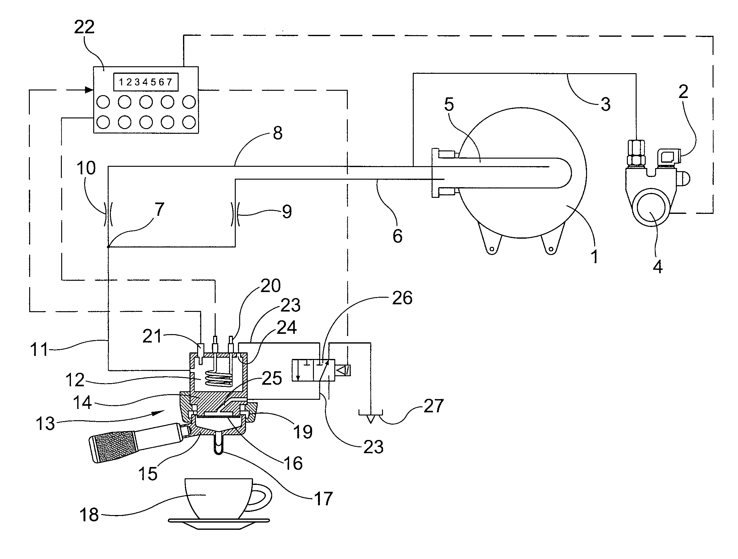
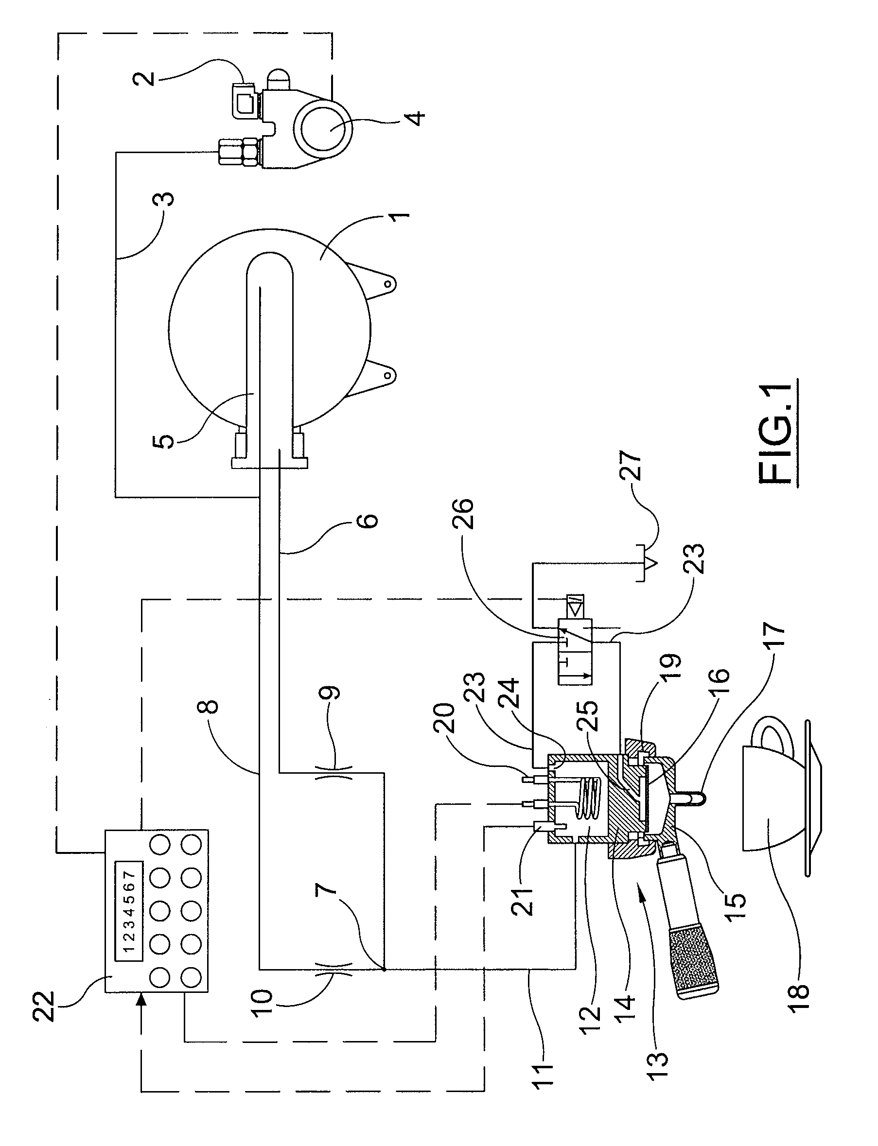
[0018]With reference to the drawing, the reference 1 indicates a conventional boiler for an espresso coffee machine, for the production of hot water and steam. The boiler is fed, in a conventional manner, not indicated in the drawing, by an external cold water source indicated by 2.

[0019]The same water source 2, via a pipe 3 and a pump 4, feeds a heat exchanger 5, also conventional in an espresso coffee machine, and positioned within the boiler 1.

[0020]The outlet of the heat exchanger 5, via a pipe 6, feeds heated water to a mixing point 7 which is also reached by a pipe 8 connected to the pipe 3, bringing cold water.

[0021]On the hot water pipe 6 and on the cold water pipe 8, upstream of the mixing point 7, respective flow regulators indicated respectively by 9 and 10 are inserted.

[0022]The flow regulators make it possible to mix the cold water with the hot water in such a way as to obtain a flow of hot water at a predetermined temperature T1 in the pipe 11 which, downstream of the ...


PUM


Abstract

A coffee machine for producing and dispensing coffee-based beverages, comprising: a water supply pipe (11); at least one dispensing device (13) comprising an infusion unit (15) apt to contain coffee powder, wherein said dispensing device (13) includes an infusion body (14) apt to admit water into said infusion unit (15) when said infusion unit is engaged with said dispensing device (13), a heating chamber (12) in fluid communication with the supply pipe (11), the heating chamber (12) comprising heating means (20) and being provided with an outlet (24) for permitting the admission of water at a dispensing temperature (T2) into a connecting pipe (23) in fluid communication with the infusion body (14) via a shut-off valve (26). The water supply pipe (11) is in fluid communication with a source of water (7) at a feed temperature (T1) and thermally coupled to a heat source (5), the feed temperature (T1) being less than said dispensing temperature (T2).

Description

BACKGROUND OF THE INVENTION[0001]1. Field of the Invention[0002]The present invention relates to a coffee machine for producing and dispensing coffee-based beverages.[0003]2. Background Art[0004]Coffee, as a beverage, has always been widely used and prized; nowadays, in fact, it occurs in numerous varieties, which differ from one another both in the starting mixture, and in the method of extraction of the beverage.[0005]In particular, espresso coffee is a beverage obtained instantaneously by using a coffee machine which passes hot water through a layer of ground coffee contained in an infusion chamber, generally a metal filter. The water which passes through the layer of coffee must be heated to a certain temperature and is subjected to a certain pressure, where the optimum pressure and temperature are selected also according to the starting mixture. Typically, the temperature of the water admitted into the infusion chamber is between around 88 and 98° C. and the pressure varies fro...

Claims


Application Information

Patent Timeline
Patent Type & Authority Applications(United States)
IPC IPC(8): A47J31/44
CPCA47J31/56A47J31/465
Inventor COCCIA, ANDREAVOLONTE, CLAUDIO
Owner GRUPPO CIMBALI SPA
Learn More