Airfoil System for Cruising Flight

a technology of airfoil and cruising flight, which is applied in the direction of airflow influencers, influencers by vortices, air-flow influencers, etc., can solve the problem that airfoil systems are not equipped to optimize “over the wing” airflow for fuel efficiency, and achieve the effect of improving aerodynamic efficiency

Inactive Publication Date: 2009-12-17
NASA
View PDF16 Cites 14 Cited by
  • Summary
  • Abstract
  • Description
  • Claims
  • Application Information

AI Technical Summary

Benefits of technology

[0007]Accordingly, it is an object of the present invention to provide an airfoil system that improves aerodynamic efficiency for an aircraft operating in the cruising regime.

Problems solved by technology

However, these airfoil systems are not equipped to optimize “over the wing” airflow for fuel efficiency during an aircraft's cruising operation regime.

Method used


Image

  • Airfoil System for Cruising Flight
  • Airfoil System for Cruising Flight
  • Airfoil System for Cruising Flight

Examples


Embodiment Construction

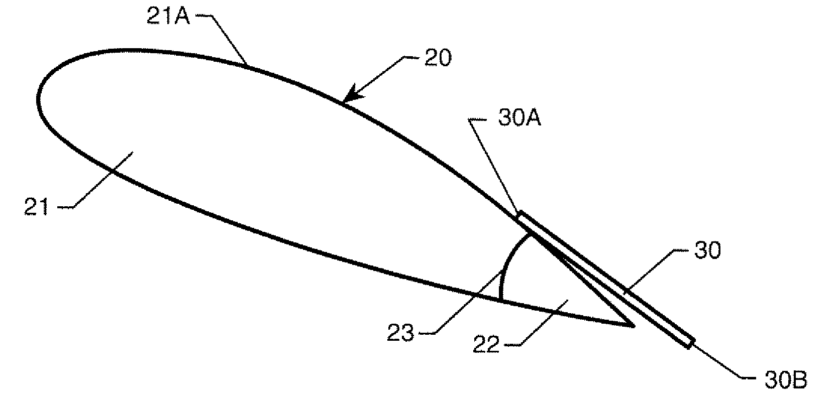
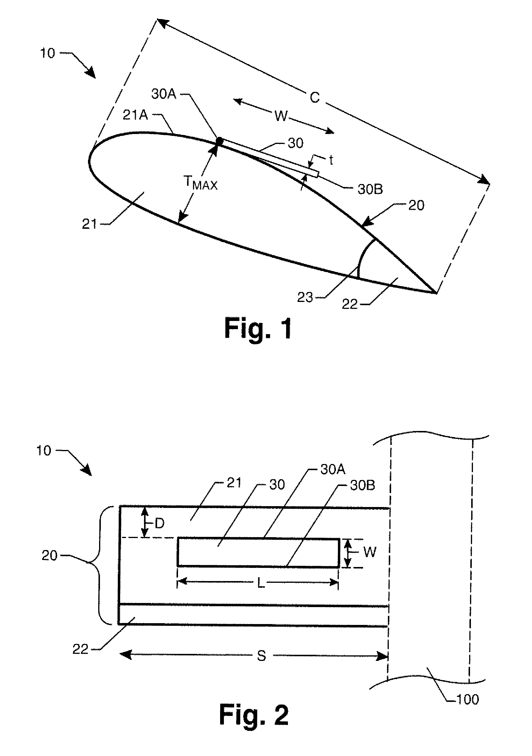
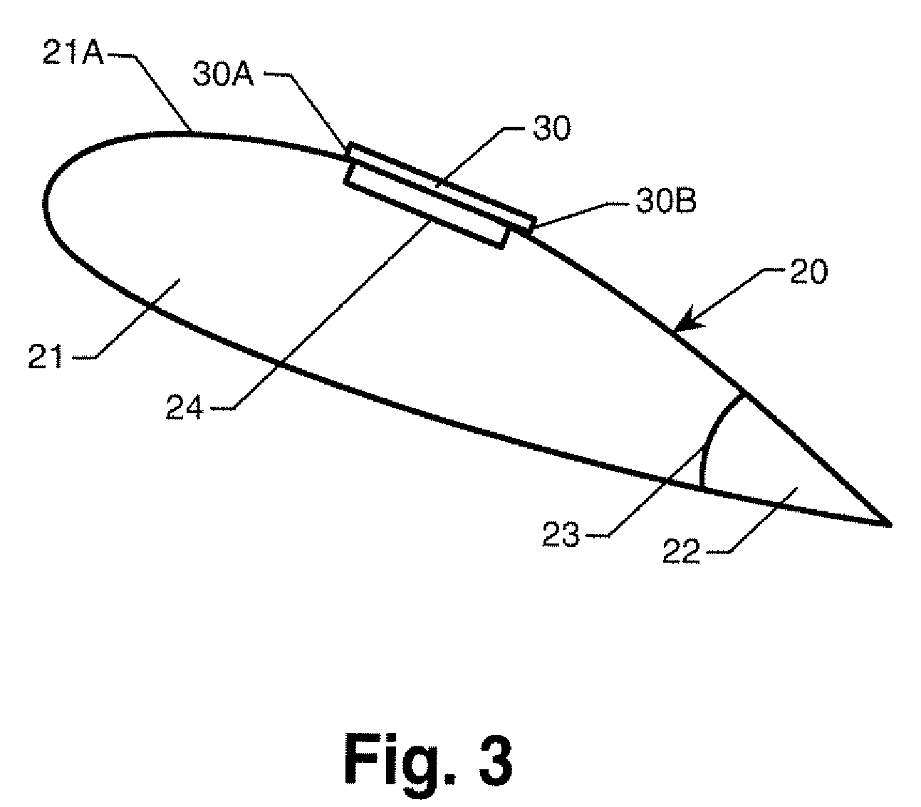
[0017]Referring now to the drawings and more particularly to FIGS. 1 and 2, an airfoil system in accordance with an embodiment of the present invention is shown and is referenced generally by numeral 10. Airfoil system 10 will be coupled on one side thereof to the fuselage 100 of an aircraft. The particular type of fuselage is not a limitation of the present invention.

[0018]Airfoil system 10 includes a main airfoil body 20 and a flexible element or strip 30. Airfoil body 20 is any conventional airfoil / wing having a rigid main body 21 and a rigid flap (or flaps) 22 coupled to main body 21 such that flap(s) 22 blend into main body 21 while being movable with respect thereto at a point of separation 23. As is well known in the art, flap(s) 22 are moved into the air flowing around airfoil body 20 during take off and landing operations. Coupling / moving mechanisms (not shown) used to create such movement are well understood in the art and are not limitations of the present invention.

[0019...


PUM


Abstract

An airfoil system includes an airfoil body and at least one flexible strip. The airfoil body has a top surface and a bottom surface, a chord length, a span, and a maximum thickness. Each flexible strip is attached along at least one edge thereof to either the top or bottom surface of the airfoil body. The flexible strip has a spanwise length that is a function of the airfoil body's span, a chordwise width that is a function of the airfoil body's chord length, and a thickness that is a function of the airfoil body's maximum thickness.

Description

[0001]Pursuant to 35 U.S.C. §119, the benefit of priority from provisional application 60 / 943,894, with a filing date of Jun. 14, 2007, is claimed for this non-provisional application.ORIGIN OF THE INVENTION [0002]The invention was made by employees of the United States Government and may be manufactured and used by or for the Government of the United States of America for governmental purposes without the payment of any royalties thereon or therefor.BACKGROUND OF THE INVENTION [0003]1. Field of the Invention[0004]This invention relates to airfoil systems. More specifically, the invention is an airfoil system that improves the aerodynamic efficiency of a winged aircraft operating in the aircraft's cruise flight regime.[0005]2. Description of the Related Art[0006]Airfoil systems utilized by most current-day aircraft include two rigid assemblies. The first rigid assembly is the main body of the airfoil that is attached to an aircraft's fuselage. The second rigid assembly comprises one...

Claims


Application Information

Patent Timeline
Patent Type & Authority Applications(United States)
IPC IPC(8): B64C3/38
CPCB64C21/00B64C23/005B64C23/04B64C21/10Y02T50/162Y02T50/166B64C23/06Y02T50/10
Inventor SHAMS, QAMAR A.LIU, TIANSHU
Owner NASA
Why Eureka
Try Eureka