Thermal transfer printer

a printer and thermal transfer technology, applied in the field of thermal transfer printers, can solve the problems of inconvenient damage to paper that never occurs, and achieve the effects of improving paper quality, and reducing the occurrence of wrinkles

Inactive Publication Date: 2009-12-17
SINFONIA TECHNOLOGY CO LTD
View PDF1 Cites 15 Cited by
  • Summary
  • Abstract
  • Description
  • Claims
  • Application Information

AI Technical Summary

Benefits of technology

[0020]With the above-described construction, the present invention can provide a novel, effective thermal transfer printer which can eliminate the lowered quality of paper due to dust retention while minimizing the occurrence of wrinkles with an ink ribbo...

Problems solved by technology

Therefore, even if dust or the like is retained at the tens...

Method used


Image

  • Thermal transfer printer
  • Thermal transfer printer
  • Thermal transfer printer

Examples


Embodiment Construction

[0026]Hereinafter, one embodiment of the present invention will be described referring to the drawings.

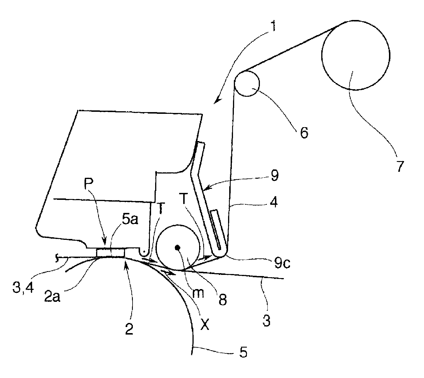
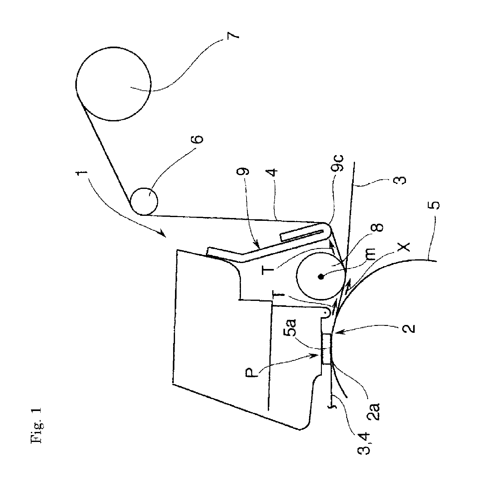
[0027]A thermal transfer printer according to the embodiment is of a line dye-sublimation type, and a thermal head structure 1 is provided with a thermal head 2, as schematically shown in FIG. 1. The thermal head 2 extends in a paper-face vertical direction orthogonal to the conveyance direction of paper 3 and an ink ribbon 4 (the direction indicated by X assigned to a superimposed position), and a plurality of heating elements (not shown) are disposed on a printing face 2a in an arrayed manner so as to be selectively heated based upon an external print signal. A platen roller 5 is rotatably arranged at an opposite position of this thermal head 2, and an outer circumferential face 5a is opposed to the printing face 2a of the thermal head.

[0028]The thermal head 2 is drivable to be elevated by means of a head drive mechanism (not shown). In the head-down state shown, the printing fac...


PUM


Abstract

A thermal transfer printer includes: a pealing roller which is disposed downstream of a printing position set between a thermal head and a platen roller and defines a peeling start position of an ink ribbon; and a tension plate which is disposed on a further downstream side than the peeling roller and slidably stretches the ink ribbon under a tension relative to the printing position, via the peeling roller. With a back tension being ensured by means of the tension plate to prevent slackness of the ink ribbon, the peeling roller performs peeling, thereby avoiding retention of dust or the like and the lowered quality of paper due to such retention. In this manner, problems such as wrinkles occurring with the ink ribbon are eliminated without damaging paper, and further, improvement of printing quality is compatible with that of paper quality, through a design based upon a mechanism concerning the occurrence of wrinkles.

Description

BACKGROUND OF THE INVENTION[0001]1. Field of the Invention[0002]The present invention relates to a thermal transfer printer to cope with a problem with the occurrence of flaws on paper due to the dust or the like retained at a peeling position or a problem with non-uniform printing due to wrinkles occurring with an ink ribbon.[0003]2. Description of the Related Art[0004]In a thermal transfer printer employing an ink ribbon, the ink ribbon and paper are sandwiched between a thermal head and a platen roller, a heat is imparted to the ink ribbon by means of the thermal head, and dyestuff of the ink ribbon is transferred to paper. The ink ribbon needs to be peeled and taken up after printing. Therefore, a peeling member is disposed downstream of a printing position, so that the ink ribbon is guided in a direction departing from the paper, as disclosed in JP-A 2002-144614 (hereinafter, referred to as Patent Document 1).[0005]In the Patent Document 1, a peeling plate is employed as a peel...

Claims


Application Information

Patent Timeline
IPC IPC(8): B41J2/325
CPCB41J35/06B41J2/325
Inventor FUKUTANI, ATSUSHIUEDA, TOMOAKI
Owner SINFONIA TECHNOLOGY CO LTD
Why Eureka
Try Eureka