
Golf club shaft with adjustable stiffness

a golf club shaft and adjustable technology, applied in the field of golf equipment, can solve the problems of shaft being bent toward the ball at the time of impact, excessive lofting, and decelerating club face, so as to increase the amount of force, increase the axial tension of the tensioning material, and increase the stiffness of the shaft

Inactive Publication Date: 2009-12-17
SIMONIS STEVEN F
View PDF5 Cites 0 Cited by
  • Summary
  • Abstract
  • Description
  • Claims
  • Application Information

AI Technical Summary

Benefits of technology

"The invention is a golf club shaft made of graphite that has a hollow interior and tapers towards the head-end and grip-end. A strand of tensioning material is inserted inside the shaft and runs along its length. One end of the tensioning material is attached to the club head tip and the other end is retained by a manually adjustable tensioner assembly at the grip-end. A rubber golf club grip is fitted over both the tensioner assembly and the grip-end of the shaft. The stiffness of the shaft can be adjusted by manipulating the tensioner assembly to increase or decrease the force that pushes the shaft in a straight configuration."

Problems solved by technology

A shaft that is not properly matched to a particular golfer's swing can result in weaker ball contact as well as a variety of mishits.
If a player uses a shaft that is too flexible for his / her particular swing, the shaft will kick prematurely and will flex past a straight position before contact, causing the shaft to be bent toward the ball at the time of impact.
The result is a club face that is decelerating, overly shut, and excessively lofted when it meets the ball.
Given an otherwise good swing by the player, the ball will tend to fly too high, to the left of the intended target (for a right-handed player), and short.
Conversely, if a player uses a shaft that is too stiff for his / her swing, the shaft will kick too late and will be bent away from the ball at the time of impact.
Again, given an otherwise good swing by the player, the ball will tend to fly too low, to the right of the intended target (for a right-handed player), and short.
If a particular golfer is best matched with a shaft having a flex rating that falls somewhere between those that are commercially available, that golfer is forced to sacrifice some measure of performance and feel and must choose a shaft that is either too stiff or too flexible for his or her swing.

Method used


Image

  • Golf club shaft with adjustable stiffness
  • Golf club shaft with adjustable stiffness
  • Golf club shaft with adjustable stiffness

Examples


Embodiment Construction

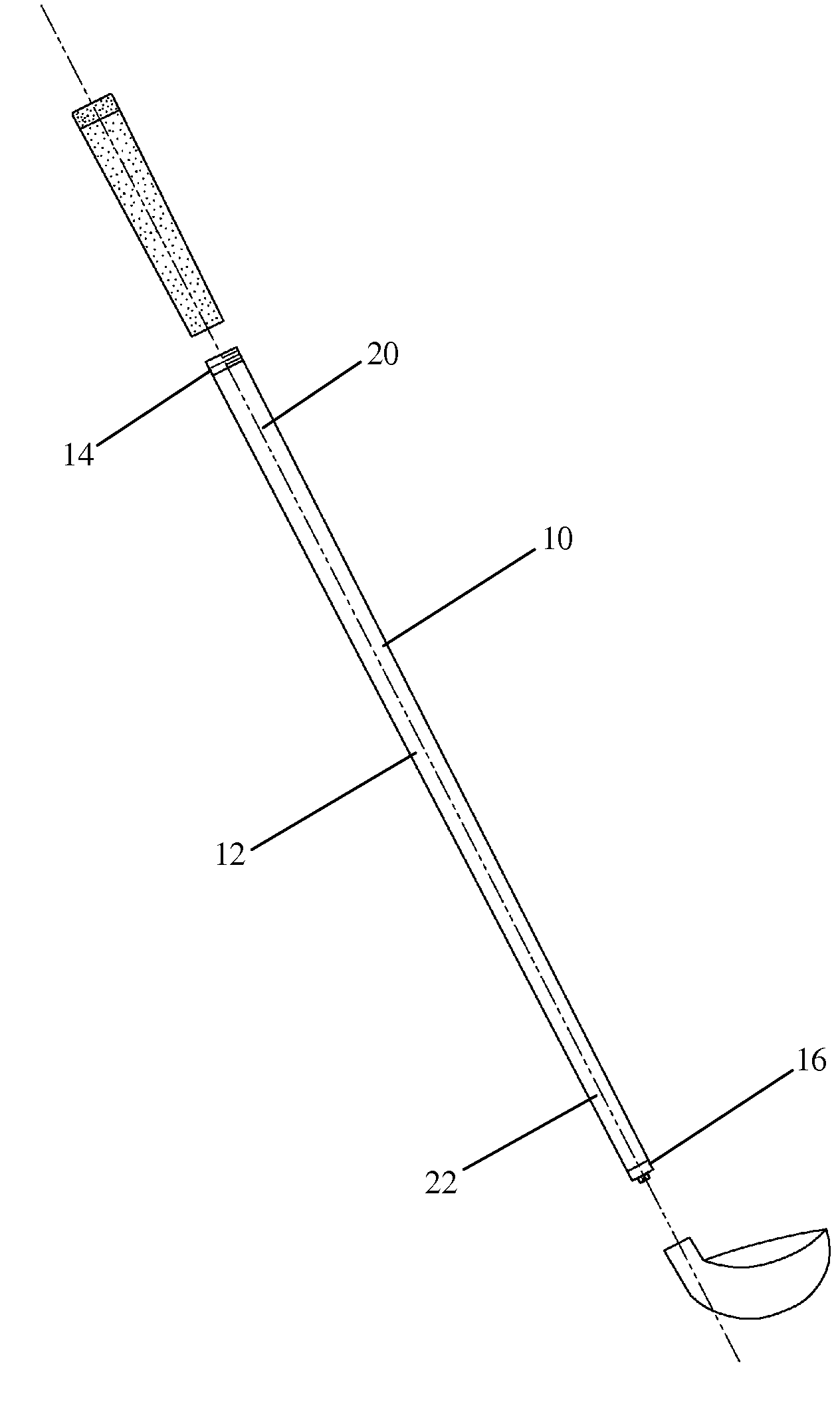
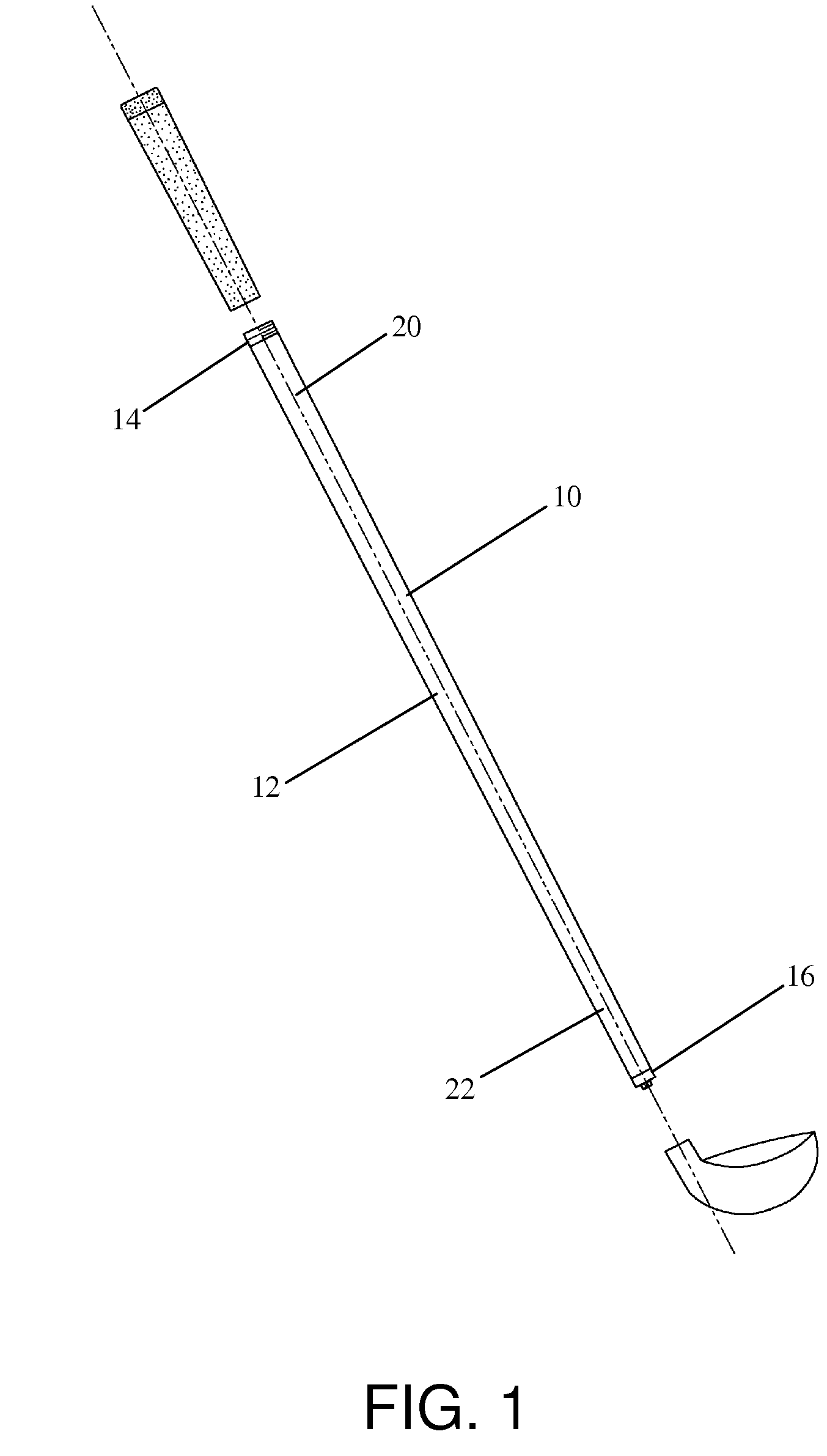
[0020]Referring to FIGS. 1-3, the adjustable shaft 10 has a conventional graphite golf club shaft 12, a tensioner assembly 14, a retainer assembly 16, and a tensioning member 18. Referring to FIG. 1, the conventional shaft 12 is a tapered, tubular body with a wide grip-end 20 and a narrow head-end 22. The shaft 12 is a standard, 43 inch, regular flex driver shaft, although the length and the flex of the shaft 12 may be varied to suit a particular application.

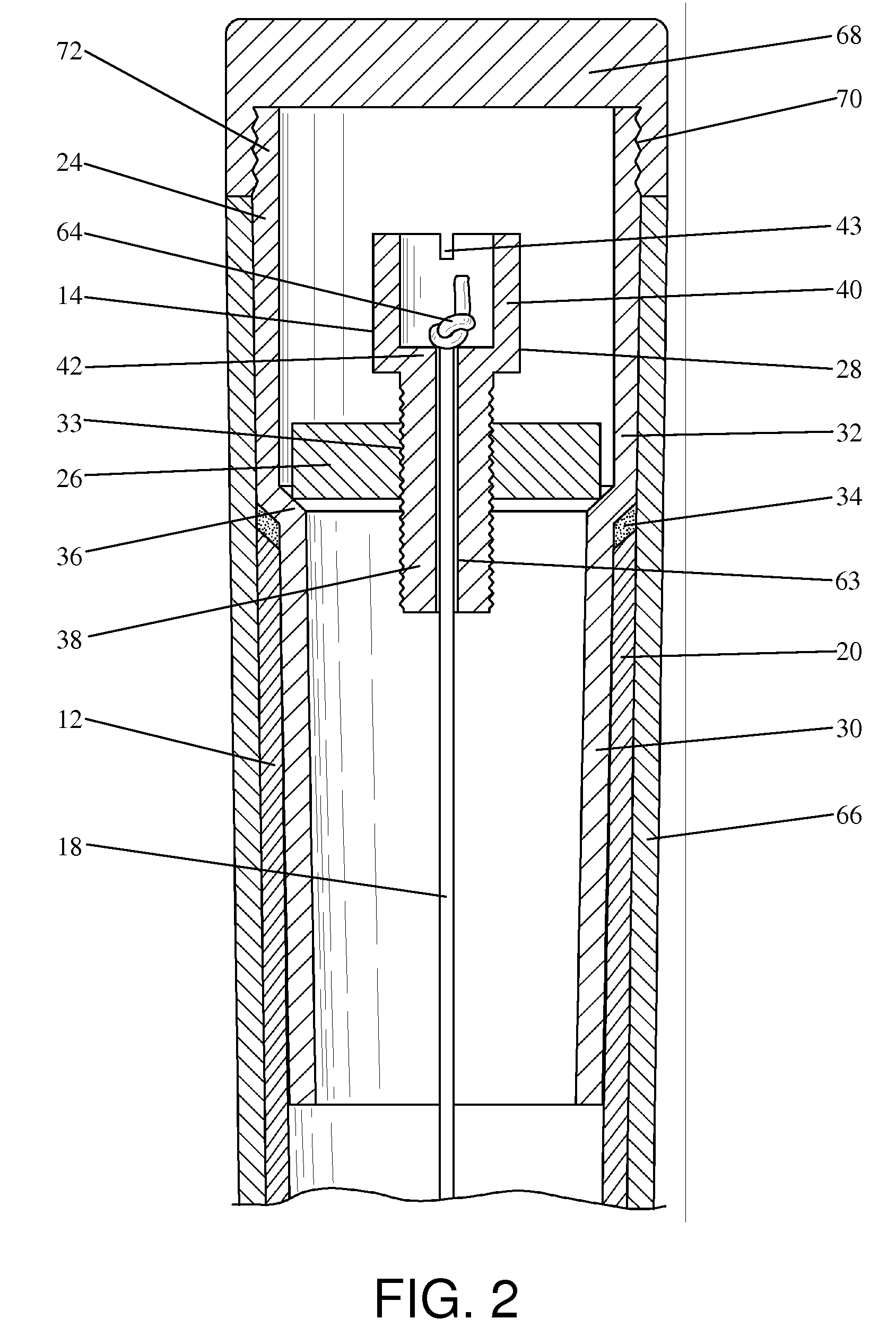
[0021]Referring to FIG. 2, the tensioner assembly 14 has a golf club shaft extension 24, a tensioning nut 26, and a tensioning barrel 28. The shaft extension 24 is of a conventional type that will be familiar to those skilled in the art, having a narrow mounting portion 30 and a wide extending portion 32. The extension 24 is mounted to the grip-end 20 of the shaft 12 in a conventional manner, with the mounting portion 30 within the shaft 12 and the extending portion 32 protruding approximately 1 inch from the shaft 12. The exten...


PUM


Abstract

A golf club shaft having adjustable stiffness. An elongated tensioning member extends through the shaft and is mounted to both ends of the shaft. A tensioner assembly is mounted to the shaft and is connected to the tensioning member for allowing manual adjustment of the axial tension in the tensioning member, thereby allowing a technician or a user to increase or decrease the stiffness of the shaft as desired.

Description

BACKGROUND OF THE INVENTION[0001]1. Field of the Invention[0002]This invention relates generally to the field of golf equipment and relates more particularly to an improved golf club shaft with manually adjustable stiffness.[0003]2. Description of the Related Art[0004]Golfers of all skill levels are continually striving to increase the distance and accuracy of their golf shots. With the constant introduction of new materials and manufacturing methods to the sport of golf, equipment is playing an ever more important role in overall game improvement. Golf clubs, in particular, have benefited greatly from recent advances in technology. Larger club heads, titanium faces, and graphite shafts are just a few of the innovations that are enabling players to hit the ball further and straighter than ever before.[0005]Widely regarded as the “engine” that drives the head of a golf club, a club's shaft has a substantial effect on a golfer's ability to achieve optimal contact between the club face...

Claims


Application Information

Patent Timeline
Patent Type & Authority Applications(United States)
IPC IPC(8): A63B53/00
CPCA63B53/10A63B53/12A63B59/0088A63B59/0014A63B53/16A63B53/14A63B60/06A63B60/08A63B60/10A63B60/22A63B60/50A63B60/00A63B60/0081
Inventor SIMONIS, STEVEN F.
Owner SIMONIS STEVEN F
Learn More