Light guide for endoscopes

Inactive Publication Date: 2009-12-17
FUJIFILM CORP
View PDF33 Cites 4 Cited by
  • Summary
  • Abstract
  • Description
  • Claims
  • Application Information

AI Technical Summary

Benefits of technology

[0033]FIG. 12A and FIG. 12B are diagrams for explaining the advantageous effects of the present invention.
[0034]FIG. 13 is a diagram that schematically illustrates the cross section of a portion of a conventional light guide for endoscopes.

Problems solved by technology

There is a problem that first facets that function as light input portions and second facets that function as light output portions of conventional light guides for endoscopes, which are constituted by bundling a plurality of thin optical fibers together, are easily damaged.

Method used


Image

  • Light guide for endoscopes
  • Light guide for endoscopes
  • Light guide for endoscopes

Examples


first embodiment

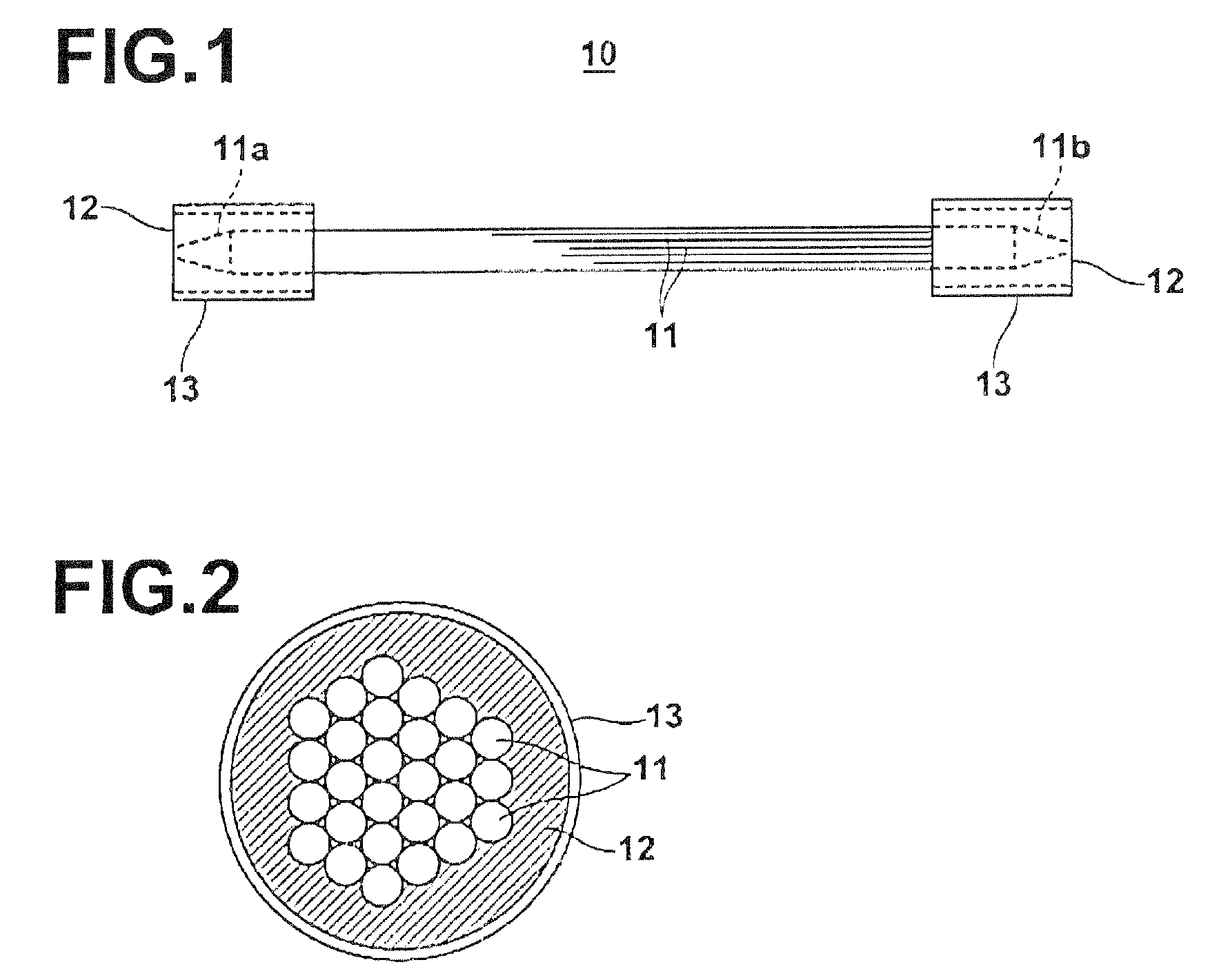
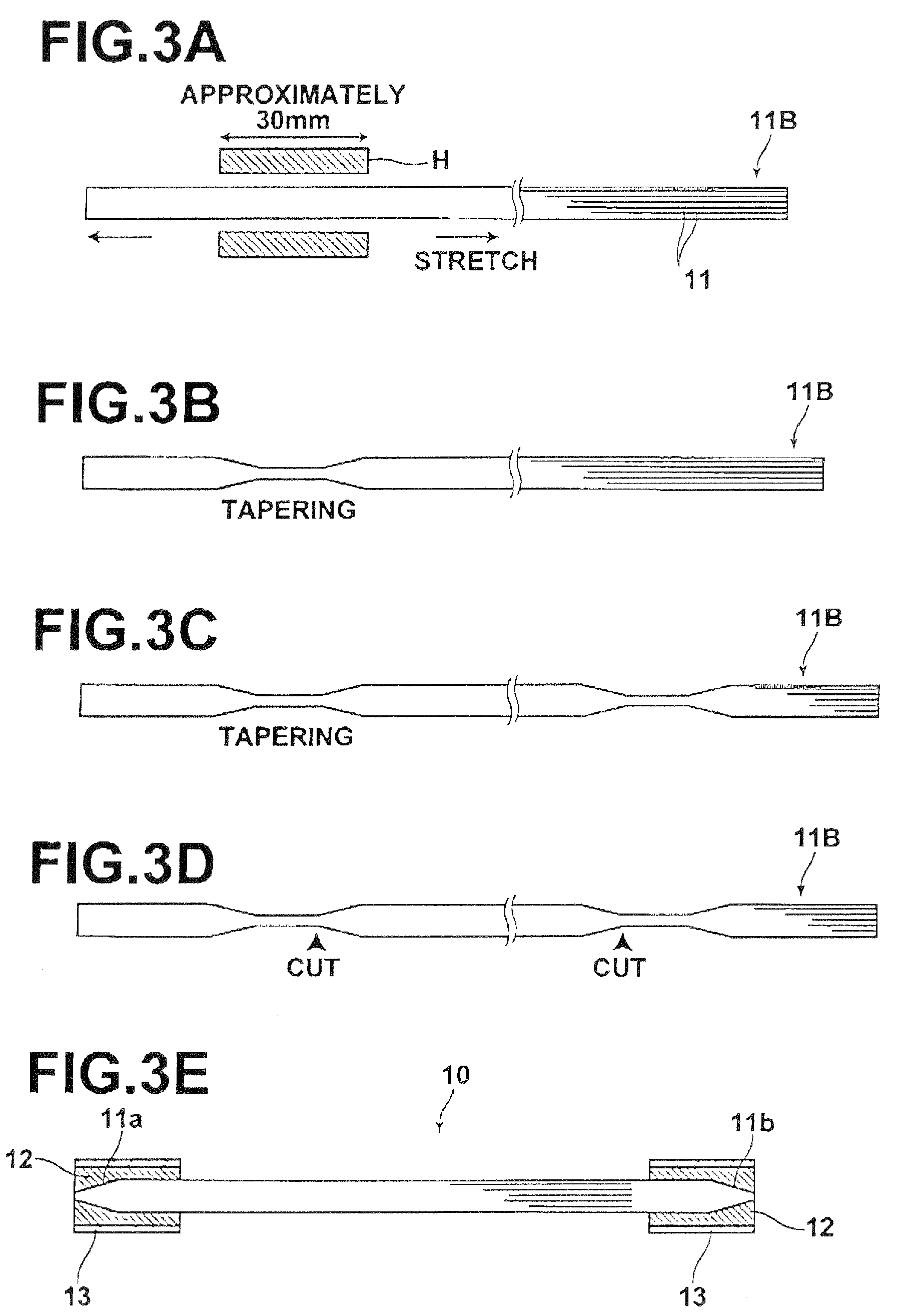
[0036]FIG. 1 is a side view that illustrates a light guide 10 for endoscopes according to the present invention. The light guide 10 for endoscopes is constituted by a plurality of bundled multi mode optical fibers 11 across its entire length. A first end portion 11a (toward the left in FIG. 1) and a second end portion 11b (toward the right in FIG. 1) of the bundled multi mode optical fibers 11 are housed in cylindrical connector housings 13, and fixed therein by a filling adhesive 12.

[0037]The first end portion 11a and the second end portion 11b are both of tapered shapes. The first end portion 11a functions as a light input portion, the facet of which an illuminating light beam enters through. The second end portion 11b functions as a light output portion, the facet of which the illuminating light beam is output through. Note that the number of optical fibers 11 at the tapered first end portion 11a and the tapered second end portion 11b is the same as at the other portions of the l...

second embodiment

[0047]The light guide 20 for endoscopes of the second embodiment differ from the light guide 10 for endoscopes illustrated in FIG. 1 and FIG. 2 in that a concave transparent member 21 is provided in close contact with the end facet of the second end portion 11b. By the transparent member 21 being provided, the illuminating light beam which is output from the end facet of the second end portion 11b is diffused by the effect of the concave shape of the transparent member 21. Accordingly, an advantageous effect that the illuminated range can become even wider is obtained.

[0048]Next, another advantageous effect which is obtained by the present invention will be described. FIG. 5 is a sectional side view of the front end portion of an endoscope, equipped with the light guide 10 of the present invention and an imaging element 30 such as a CCD for obtaining images of illuminated observed portions. FIG. 6 is a front view of the front end portion of the endoscope of FIG. 5. Note that referen...


PUM


Abstract

A light guide for endoscopes is constituted by a plurality of multimode optical fibers, of which at least a portion is bundled. The light guide propagates illuminating light beam that enters from a first end facet thereof to a second end facet thereof, to emit the illuminating light beam onto a portion to be observed. The light guide includes: a light input portion formed by the bundled plurality of multimode optical fibers; and a light output portion formed by the bundled plurality of multimode optical fibers. At least one of the light input portion and the light output portion is shaped in a tapered shape, while the number of multimode optical fibers at the light input portion and the light output portion are the same as that at other portions of the light guide.

Description

BACKGROUND OF THE INVENTION[0001]1. Field of the Invention[0002]The present invention is related to a light guide for endoscopes, that is, a light guide that propagates light therethrough such that portions which are observed with an endoscope are illuminated.[0003]2. Description of the Related Art[0004]Conventionally, endoscopes are in wide use to observe and perform surgical procedures on portions within body cavities of humans. Flexible light guides for illuminating the observed portions of subjects are employed in these endoscopes. Note that in cases that surgical procedures are performed on portions, observation thereof is necessary. Therefore, portions on which surgical procedures are performed will also be referred to as “observed portions” in the present specification.[0005]At least a portion of this type of light guide is generally constituted by a plurality of thin multi mode optical fibers which are bundled, to impart flexibility thereto. Japanese Unexamined Patent Public...

Claims


Application Information

Patent Timeline
IPC IPC(8): A61B1/07
CPCA61B1/07A61B1/00167G02B23/2469G02B6/06
Inventor SHIMOTSU, SHINICHI
Owner FUJIFILM CORP
Why Eureka
Try Eureka