Method, apparatus and plant for manufacturing shell structures

a technology for working shells and manufacturing methods, applied in the direction of manufacturing tools, soldering devices, auxillary welding devices, etc., can solve the problem of insufficient re-use of known production methods and equipments, possibly with relatively contained adaptations

Inactive Publication Date: 2009-12-24
ALENIA AERMACCHI +1
View PDF24 Cites 27 Cited by
  • Summary
  • Abstract
  • Description
  • Claims
  • Application Information

AI Technical Summary

Problems solved by technology

Manufacturing an airplane in this way involves among other things unknown problems of industrialization and concerning production equipments: in fact the known production methods and equipments have been used up to now for manufacturing traditional ci...

Method used


Image

  • Method, apparatus and plant for manufacturing shell structures
  • Method, apparatus and plant for manufacturing shell structures
  • Method, apparatus and plant for manufacturing shell structures

Examples


Embodiment Construction

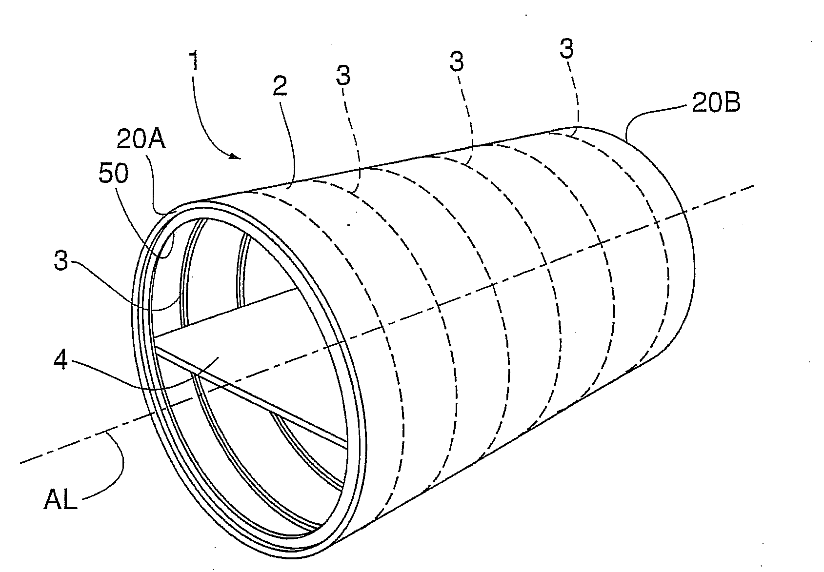
[0026]FIG. 1 schematically shows the load beaannular structure of a first embodiment of a shell structure obtainable with the method according to the invention: such embodiment of shell structure is a so-called “barile” (“barrel” in the Anglo-Saxon technical language), having a tubular shape.

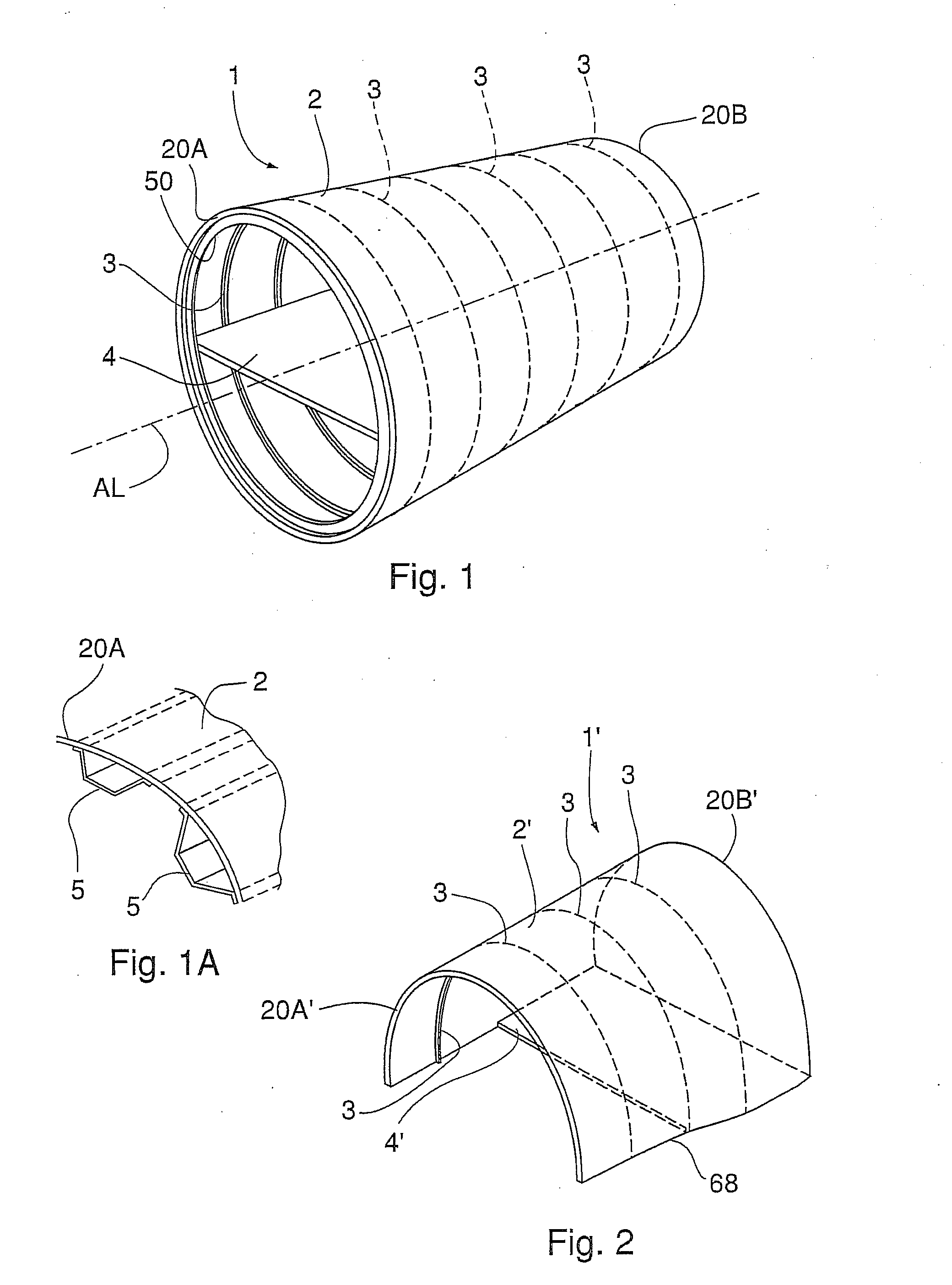
[0027]Such structure, referred to as the overall numeral 1, comprises a cylindrical tubular shell 2—also referred to as “starting shell”, in the present description—, a plurality of transversal strengthening ribs 3, approximately arc-shaped and arranged transversally to the longitudinal AL axis of the barrel, and a floor 4.

[0028]In the present embodiment the raw shell 2, extending along the longitudinal AL axis, defines an inner through cavity 50 and is made of a suitable composite material, such as carbon fibers drown in a polymeric matrix. The shell 2 is longitudinally strengthened with a plurality of longitudinal ribs 5 (FIG. 1A), arranged longitudinally to the AL axis and made of composite m...


PUM

PropertyMeasurementUnit
Currentaaaaaaaaaa
Currentaaaaaaaaaa
Currentaaaaaaaaaa

Abstract

According to the invention, a shell handling carriage (19) is provided with grippers (194) which grip the end edges of a shell (2) made of composite material still fixed to a molding drum (11). An expeller strut (13) prevents the drum (11) from moving while the carriage (19) translating 5 removes the shell (2) from the drum (11). The shell (2) is then transported by the carriage (19) to a working station in which robots rivet the transversal ribs on it. The transversal ribs reach the robot working position orderly arranged on a self-moving rib store, which is inserted in the shell (2) itself.

Description

FIELD OF THE INVENTION [0001]The present invention relates to a method, an equipment and a plant for working shell structures, in particular but not limited to shell structures of aircrafts.BACKGROUND ART [0002]Currently new techniques are under development, for manufacturing large-capacity airplanes for civil use and for transporting passengers. According to such techniques, the load beaannular structure of the aircraft fuselage is mostly made up of composite materials, such as carbon fibers buried in suitable resins. A technique currently under way of development consists in assembling the airplane fuselage by connecting a plurality of cylindrical and non-cylindrical segments, currently named “barrel” in the Anglo-Saxon technical jargon, or correspondingly “barili” in the Italian jargon.[0003]The barrels that will form an aircraft can be manufactured by different constructors, and delivered already provided with floors, seats, windows and doors before the complete fuselage is asse...

Claims


Application Information

Patent Timeline
IPC IPC(8): B21D53/92B64C1/00B23Q7/04
CPCB64F5/0036Y10T29/53539Y10T29/49622Y10T29/53991Y10T29/53974B64F5/50
Inventor BISIACH, GIUSEPPE COGNOMEBISIACH, BRUNO COGNOME
Owner ALENIA AERMACCHI
Why Eureka
Try Eureka