Cyclonic separating apparatus

a technology of cyclonic separation and separating apparatus, which is applied in the direction of isotope separation, combination devices, applications, etc., can solve the problems of reducing the efficiency at which the cyclonic separation apparatus operates, the arrangement of the cyclonic separation apparatus may be less effective, and the separation of dirt and dust will move towards the outlet, so as to reduce the risk of re-entrainment of separated dirt, the risk of fine dirt and dust deposited in the collector can be minimised

Inactive Publication Date: 2009-12-24
DYSON TECH LTD
View PDF12 Cites 120 Cited by
  • Summary
  • Abstract
  • Description
  • Claims
  • Application Information

AI Technical Summary

Benefits of technology

[0008]It is an object of the present invention to provide cyclonic separating apparatus which reduces the risk of re-entrainment of dirt and dust separated from an airflow whilst minimising any detrimental effect on the separation efficiency of the cyclonic separating apparatus. It is a further object to provide cyclonic separating apparatus which minimises the risk of re-entrainment of dirt and dust separated from an airflow when the cyclonic separating apparatus is moved away from a vertical orientation.
[0009]The invention provides cyclonic separating apparatus for separating particles from a dirt- and dust-laden airflow comprising a cyclone for separating and collecting dirt and dust from the dirt- and dust-laden airflow, the cyclone having an air inlet, an air outlet, a longitudinal axis and a wall, the wall comprising a first portion and a second portion spaced further from the longitudinal axis than the first portion, the first and second portions being axially spaced along the longitudinal axis, wherein the cyclone further comprises at least one lip extending from the first portion of the wall into a portion of the cyclone surrounded by the second portion of the wall. By providing a cyclone with a wall having two portions of different sizes and a lip extending from the smaller portion into the larger portion, the risk of blockages due to re-entrainment and movement of dirt and dust within the cyclonic separating apparatus is reduced.
[0011]Preferably, the lip forms a substantially straight extension of the first portion of the wall. This arrangement minimises the protrusion of the lip into the airflow whilst still reducing the risk of re-entrainment of separated dirt and dust within the cyclonic separating apparatus.
[0012]Preferably, the cyclonic separating apparatus comprises at least one further cyclone and a collector which are located downstream of the air outlet, the at least one further cyclone being arranged to deposit separated dirt and dust into the collector. More preferably, the collector has a longitudinal axis, a wall and at least one further lip extending from the wall of the collector into the collector. By providing a lip extending from the wall of the collector, the risk of re-entrainment and migration of fine dirt and dust deposited in the collector can be minimised and thus the risk of the further cyclones becoming blocked is reduced.

Problems solved by technology

This is undesirable because this dirt and dust may cause blockages in parts of the cyclonic separating apparatus such as the through-holes of the shroud.
Blocking the through-holes of the shroud will reduce the efficiency at which the cyclonic separating apparatus operates.
However, whilst this solution is useful for cyclonic separating apparatus which is orientated substantially vertically (such as in an upright machine), this arrangement may be less effective for cyclonic separating apparatus which is orientated away from the vertical.
In these circumstances, there is a risk that the separated dirt and dust will move towards the outlet of the first cyclone.
This is undesirable because the dirt and dust may block the inlet or the through-holes in the shroud.
However, the introduction of elements such as inwardly-projecting ribs or collars on the inner wall of a cyclone may also introduce unwanted effects.
For example, these elements may generate turbulence within the cyclone which may disturb the deposited dirt and dust in an undesirable way.
Further, the introduction of these elements can reduce the separation efficiency of the cyclone.

Method used


Image

  • Cyclonic separating apparatus
  • Cyclonic separating apparatus
  • Cyclonic separating apparatus

Examples


first embodiment

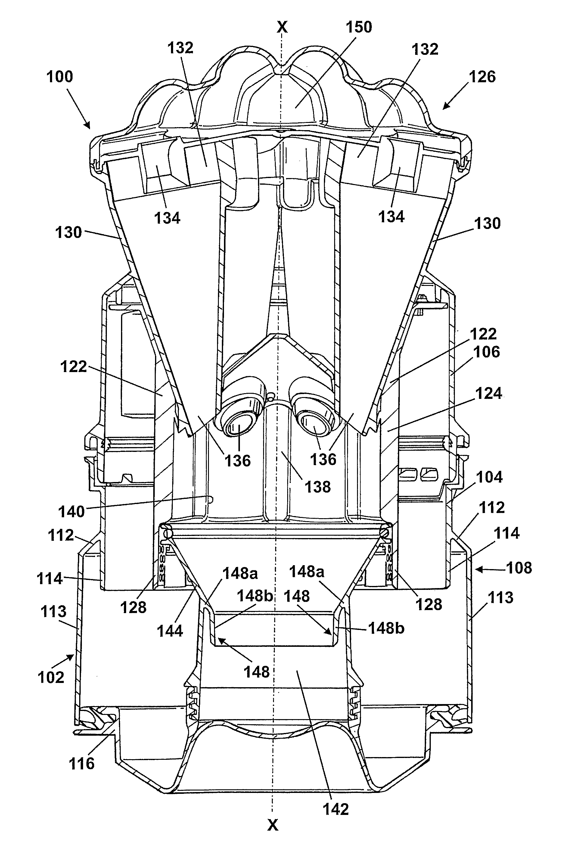
[0033]Both the lip 114 and the further lip 148 may take different configurations or shapes from those shown in the FIGS. 4 to 11 illustrate schematically eight further alternative configurations of the lip or lips which fall within the scope of the invention. In these illustrations, all detail will be omitted other than the general shape of the lip and adjoining wall portions. These configurations of lip may be applied to either the lip in the cyclone or to the further lip in the collector.

second embodiment

[0034]FIG. 4 shows the invention. In this embodiment, the cyclonic separating apparatus 200 includes a lip 202 which extends from a first portion 204 of a wall into a region surrounded by a second portion 206 of the wall. The lip 202 has a plurality of through-holes which allow air to pass but block larger particles of dirt and dust. Otherwise, the lip 202 is the same as the lip 114 described above.

third embodiment

[0035]FIG. 5 shows the invention. In this embodiment, the cyclonic separating apparatus 250 includes a lip 252 which extends from a frustoconically-shaped first portion 254 of a wall into a region surrounded by a second portion 256 of the wall. The second portion 254 of the wall is partly frustoconical-shaped and partly cylindrical.


PUM

PropertyMeasurementUnit
radiusaaaaaaaaaa
distanceaaaaaaaaaa
angleaaaaaaaaaa

Abstract

A cyclonic separating apparatus for separating particles from a dirt-laden airflow includes a cyclone for separating and collecting dirt and dust from the dirt-laden airflow. The cyclone has an air inlet, an air outlet, a longitudinal axis and a wall. The wall includes a first portion and a second portion spaced farther from the longitudinal axis than the first portion, the first and second portions being spaced along the longitudinal axis. The cyclone also includes at least one lip extending from the first portion of the wall into a portion of the cyclone surrounded by the second portion of the wall. By providing a cyclone with a wall having two portions of different sizes and a lip extending from the portion with the smaller size into the portion with the larger size, the risk of blockages due to re-entrainment and movement of dirt and dust within the cyclonic separating apparatus is reduced.

Description

REFERENCE TO RELATED APPLICATIONS[0001]This application is a national stage application under 35 USC 371 of International Application No. PCT / GB2007 / 002525, filed Jul. 6, 2007, which claims the priority of United Kingdom Application No. 0614237.6, filed Jul. 18, 2006, the contents of which prior applications are incorporated herein by reference.FIELD OF THE INVENTION[0002]The invention relates to cyclonic separating apparatus particularly, but not exclusively, for a vacuum cleaner. More particularly, the invention relates to cyclonic separating apparatus for a hand-held vacuum cleaner.BACKGROUND OF THE INVENTION[0003]Cyclonic separating apparatus is known from, for example, EP 0 042 723. This document discloses a vacuum cleaner which separates particles from an airflow using two reverse flow cyclones. The cyclones comprise a first, low-efficiency cyclone and a second, high-efficiency cyclone downstream of the first cyclone. Dirt- and dust-laden air enters through an inlet in the fir...

Claims


Application Information

Patent Timeline
Patent Type & Authority Applications(United States)
IPC IPC(8): B04C3/06
CPCA47L5/24A47L9/1625A47L9/1641A47L9/1683B04C5/08Y10S55/03B04C5/103B04C5/13B04C5/185B04C5/26B04C2009/002B04C5/10A47L5/00A47L9/16A47L9/1608A47L9/1691A47L9/1616B04C5/081A47L5/26
Inventor GOMICIAGA-PEREDA, RICARDOSTRUTT, BENJAMIN JOHN
Owner DYSON TECH LTD
Why Eureka
Try Eureka