Engine generator

Inactive Publication Date: 2009-12-24
HONDA MOTOR CO LTD
View PDF8 Cites 6 Cited by
  • Summary
  • Abstract
  • Description
  • Claims
  • Application Information

AI Technical Summary

Benefits of technology

[0006]It is therefore an object of the invention to provide an engine generator capable of preventing moisture contained in the air from being guided into the generator.
[0008]The first barrier plate causes the air sucked through the intake port to flow sideward, whereby the air flow path can be extended and the flow rate of the air can be lowered. When the air flows along the extended flow path at the lowered flow rate, the moisture contained in the air has a higher chance of falling on its own and separating from the air. Therefore, even when rainwater bounced upward off the ground or other surfaces becomes airborne moisture and water mist and enters (spatters into) the intake port, the airborne moisture and water mist can be separated from the air. In this way, the moisture contained in the air will not be guided into the generator.
[0009]Preferably, the first barrier plate has a front end and a folded portion folded at the front end and oriented downward. Water droplets adhering to the first barrier plate are guided to the folded portion by the air flowing sideward. The water droplets having been guided to the folded portion travel downward along the folded portion and fall from a lower end of the folded portion. The moisture contained in the air can thus be separated.
[0010]Desirably, the first barrier plate extends sideward and is inclined downward in the duct space in such a way that a front end is lower than the rest of the first barrier plate. Therefore, water droplets adhering to the first barrier plate flow down to the front end and efficiently fall therefrom. In this way, the moisture contained in the air is further adequately separated.
[0011]In a preferred form, the intake duct includes a second barrier plate disposed on the portion of the intake duct wall where the air flowing sideward along the first barrier plate is forced to flow upward, the second barrier plate projecting obliquely downward in such a way that a front end is in a relatively lower position. The air traveling upward along the intake duct therefore impinges on the second barrier plate, and the moisture contained in the air adheres to the second barrier plate in the form of water droplets. The water droplets adhering to the second barrier plate flow down to the front end and efficiently fall therefrom. In this way, the moisture contained in the air can be further separated.

Problems solved by technology

When the air flows along the extended flow path at the lowered flow rate, the moisture contained in the air has a higher chance of falling on its own and separating from the air.

Method used


Image

  • Engine generator
  • Engine generator
  • Engine generator

Examples


Embodiment Construction

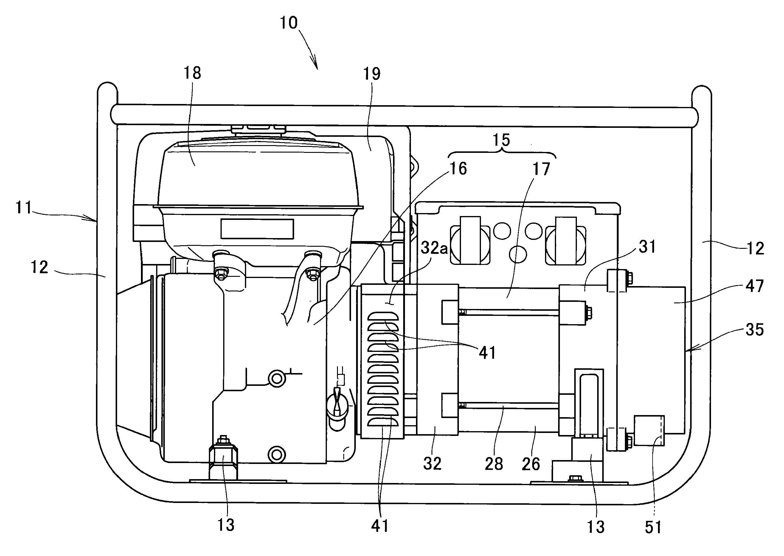
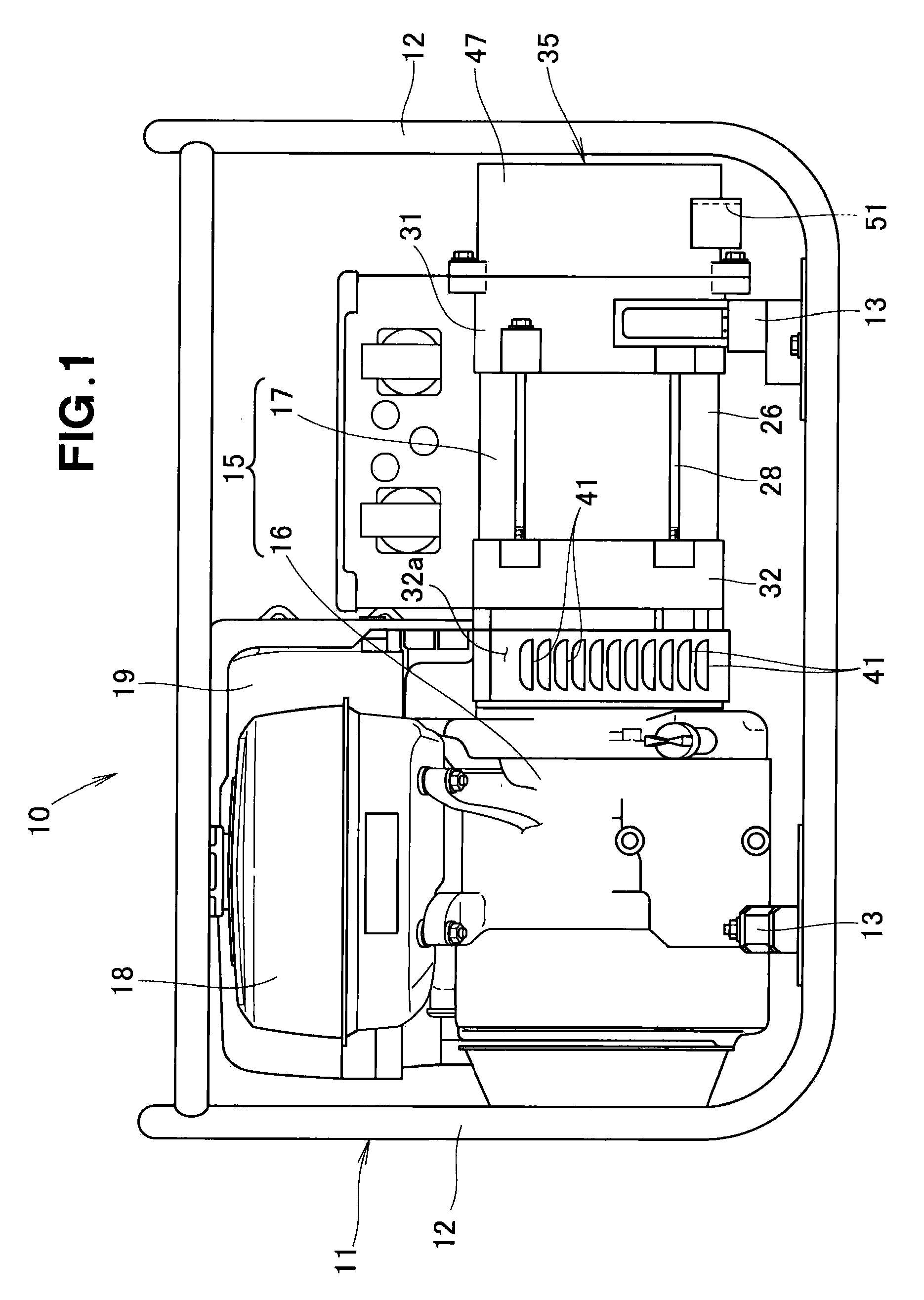
[0020]An engine generator 10 according to the embodiment shown in FIG. 1 includes a substantially cubic frame 11 comprising a plurality of columns 12 or other components, an engine-generator assembly 15 provided in the frame 11 with attachment members 13 therebetween, and a fuel tank 18 and an air cleaner 19 provided above an engine 16 in the engine-generator assembly 15.

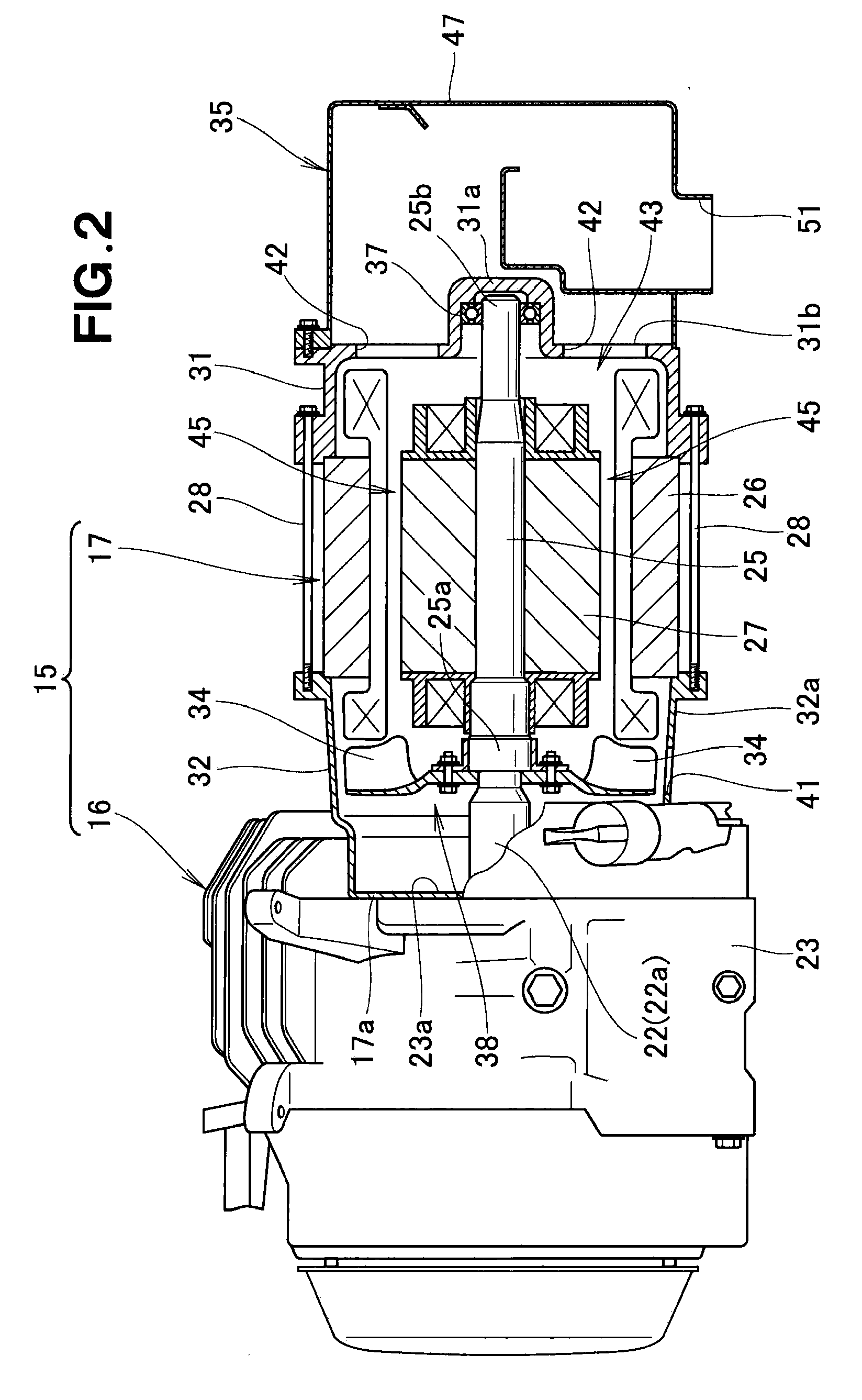
[0021]As shown in FIG. 2, the engine-generator assembly 15 according to the first embodiment includes the engine 16 and a generator 17 provided coaxially with a crankshaft (output shaft) 22 of the engine 16.

[0022]A front end 22a of the crankshaft 22 protrudes from a front wall 23a of a crankcase 23. A rear end 17a of the generator 17 is located at the front wall 23a of the crankcase 23. A rear end 25a of a drive shaft 25 of the generator 17 is coaxially connected to the front end 22a of the crankshaft 22.

[0023]The generator 17 includes a stator 26, a rotor 27 disposed in the stator 26 around the drive shaft 25, fron...


PUM


Abstract

An engine generator is disclosed in which an engine drives a generator and causes a cooling fan to rotate to cool the generator. The generator includes an intake duct having an intake port provided in a lower portion thereof and oriented downward. Moisture-containing outside air sucked through the intake port impinges on a barrier plate disposed in the intake duct. The barrier plate is located above the intake port and faces the intake port. The moisture adheres to the barrier plate in the form of water droplets, which then fall toward the intake port after having separated from the outside air.

Description

FIELD OF THE INVENTION[0001]The present invention relates to an engine generator (engine-generator assembly) in which an engine is driven to drive a generator and to rotate a cooling fan and cooling air sucked by the cooling fan is guided into the generator.BACKGROUND OF THE INVENTION[0002]Some engine generators include an air inlet on a sidewall of an enclosure, an intake duct communicating with the air inlet, and an intake port of the intake duct oriented downward. An exemplary engine generator of this type is disclosed in Japanese Utility Model Application Laid-Open Publication No. 07-030565.[0003]Outside air introduced through the intake port is guided through the intake duct and the air inlet into the generator, and cools the generator.[0004]According to the engine generator disclosed in Japanese Utility Model Application Laid-Open Publication No. 07-030565, forming the intake port of the intake duct so as to be oriented downward can prevent rainwater from directly entering the...

Claims


Application Information

Patent Timeline
IPC IPC(8): F02F1/34
CPCF02B63/044F02B63/04
Inventor FUKUDA, TORUSATOH, YUKITSURU, RYUJIYAMASHITA, KOSEI
Owner HONDA MOTOR CO LTD
Why Eureka
Try Eureka