Device for damping the lateral forces due to jet separation acting on a rocket engine nozzle

a technology of jet separation and lateral force, which is applied in the direction of vessel construction, marine propulsion, aircraft navigation control, etc., can solve the problems of limiting the level of force that is transmitted to the structure and dissipating residual kinetic energy

Inactive Publication Date: 2009-12-24
ARIANEGRP SAS
View PDF7 Cites 4 Cited by
  • Summary
  • Abstract
  • Description
  • Claims
  • Application Information

AI Technical Summary

Benefits of technology

[0006]The present invention seeks to remedy the above-mentioned drawbacks by proposing a device for damping the lateral forces due to jet separation, which device is completely reliable under all circumstances.
[0012]The force threshold is determined as a function of the maximum force that can be accepted by the drive assembly, and in particular by its actuator (e.g. constituted by a hydraulic cylinder). In practice, this force threshold corresponds to a force measured at the actuator. It can thus be understood that if the forces acting on the struts of the drive assemblies are below the determined force threshold, the struts act merely as rigid connecting rods. In contrast, once the forces acting on the struts exceed the force threshold, the struts cease to act as rigid connecting rods, limiting the level of force that is transmitted to the structure, and dissipating residual kinetic energy. As a result, the device of the invention serves to limit the forces acting on the attachment between the engine and the launcher so as to avoid breaking them. This improves launcher safety and launch pad safety.

Problems solved by technology

In contrast, once the forces acting on the struts exceed the force threshold, the struts cease to act as rigid connecting rods, limiting the level of force that is transmitted to the structure, and dissipating residual kinetic energy.

Method used


Image

  • Device for damping the lateral forces due to jet separation acting on a rocket engine nozzle
  • Device for damping the lateral forces due to jet separation acting on a rocket engine nozzle
  • Device for damping the lateral forces due to jet separation acting on a rocket engine nozzle

Examples


first embodiment

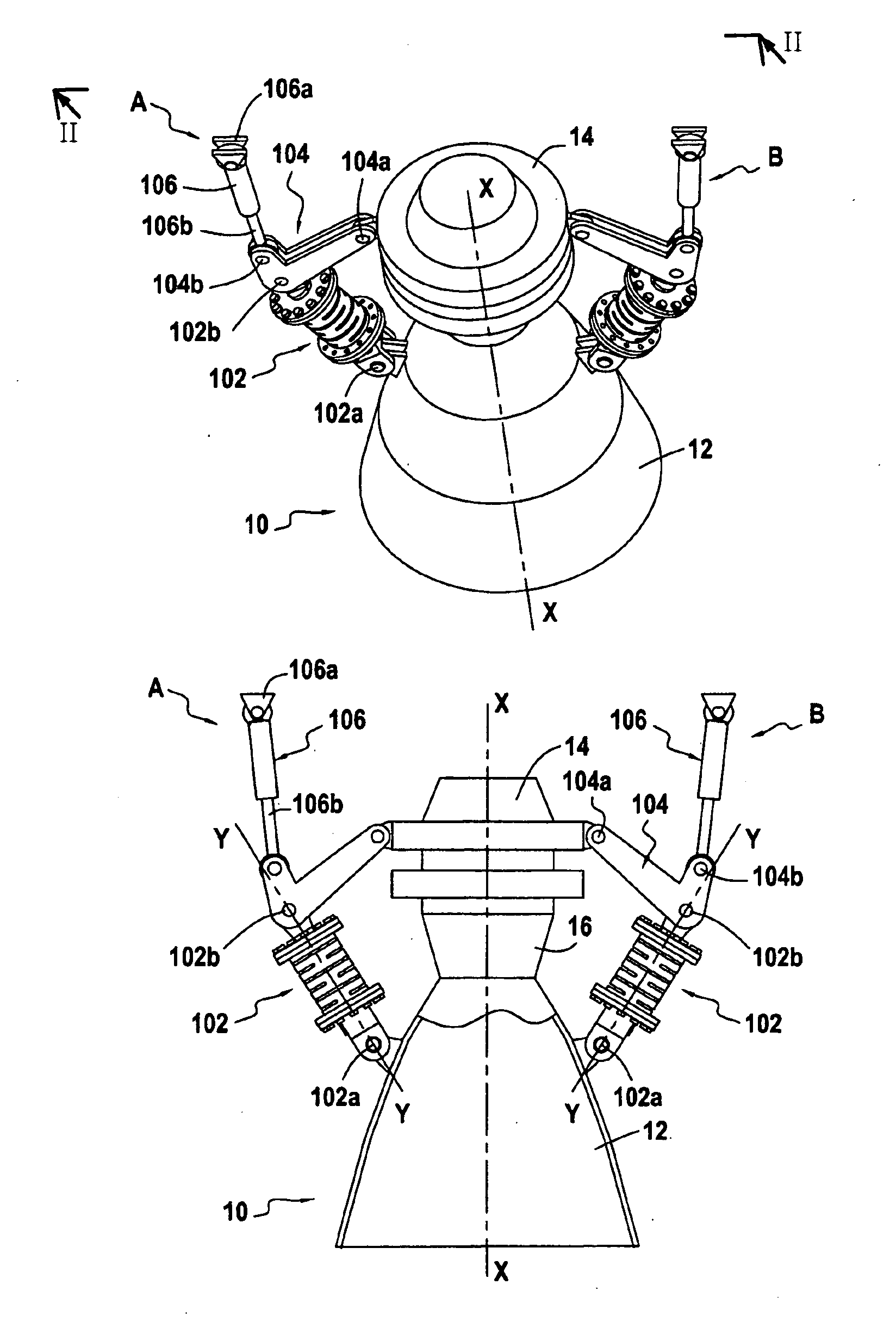
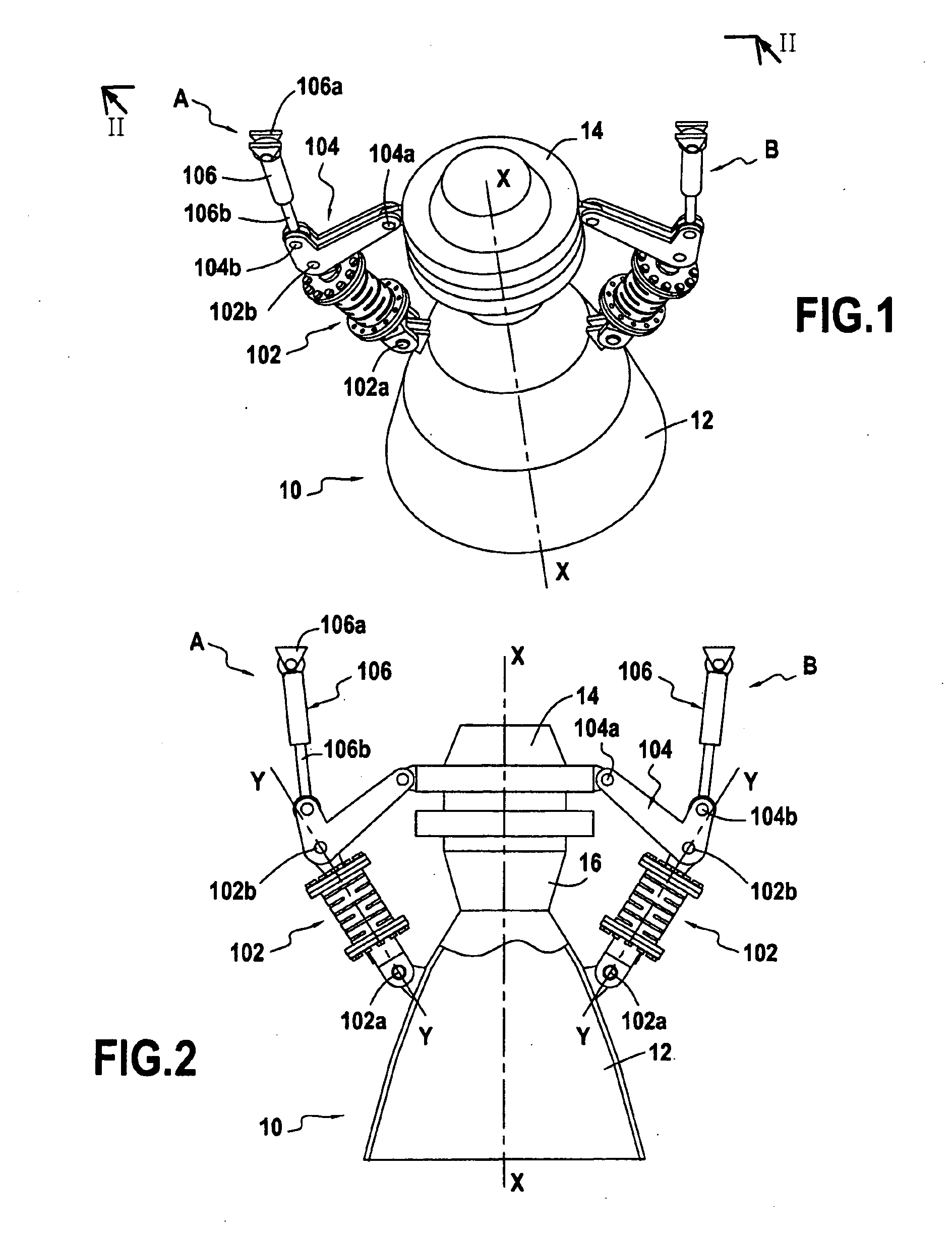
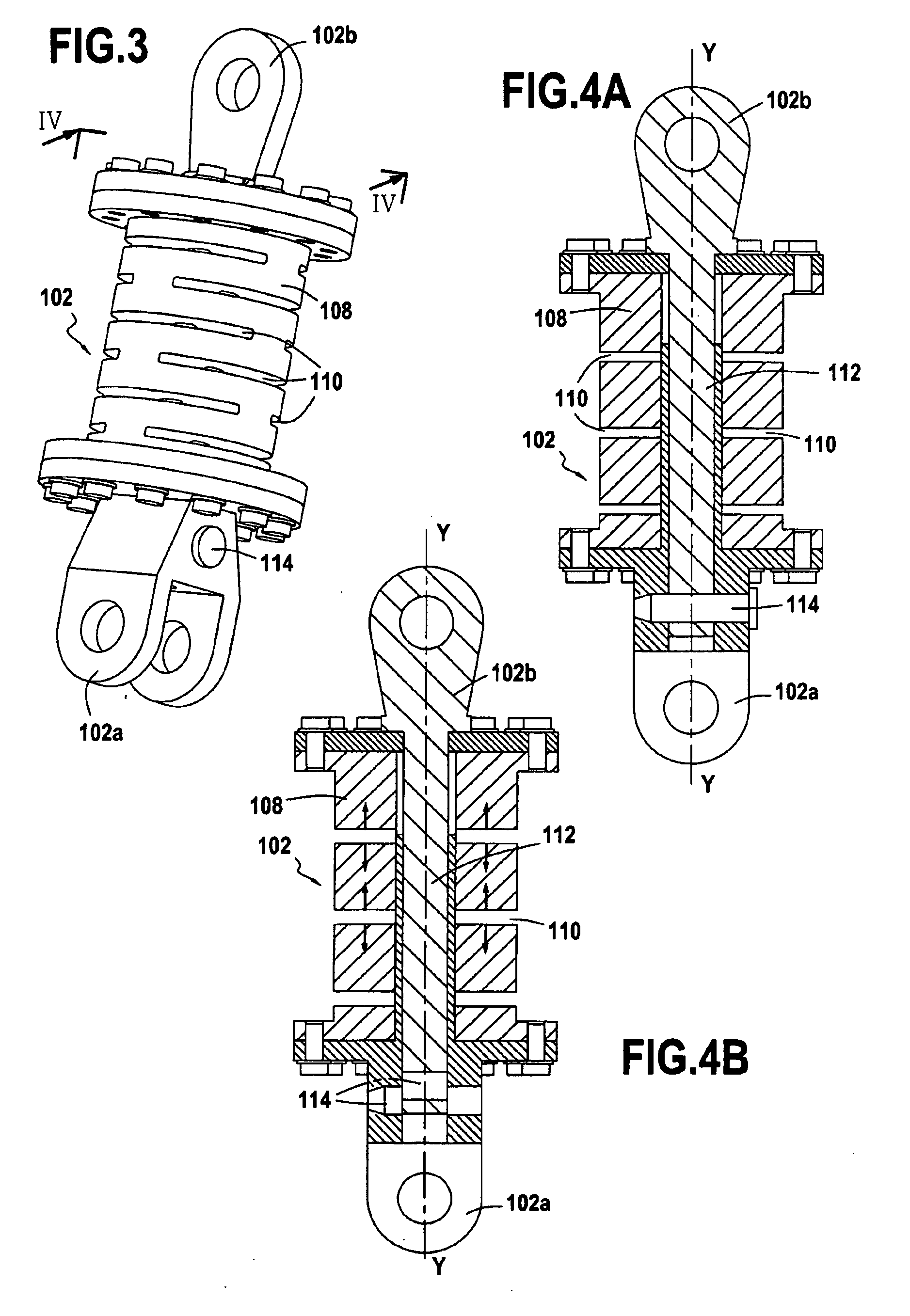
[0037]In a first embodiment, shown in FIGS. 1, 2, 3, 4A, and 4B, each strut 102 of the drive assemblies comprises a tube 108 that extends longitudinally along the main axis Y-Y of the strut and that is fastened to the two ends 102a and 102b thereof.

[0038]The tube 108 presents a plurality of circumferential slots (or notches) 110. The material in which the tube is made, and the shape, distribution, and dimensioning of the slots are selected in such a manner that under a longitudinal mechanical force, the tube can be subjected to plastic deformation (i.e. it does not return the energy absorbed) in compression or in extension (like a spring). Obtaining such plastic deformation is known to the person skilled in the art and is therefore not described in detail here.

[0039]Each strut 102 also comprises a rigid connecting rod 112 that extends longitudinally along the main axis Y-Y of the strut and that has one of its ends fastened directly to (or coinciding with) one of the ends 102b of the...

second embodiment

[0047]The principle on which this second embodiment of the jet-separation lateral force damper device operates is as follows. In the event of the jet-separation phenomenon occurring, each strut 102—and thus each rigid cover 116—is subjected to traction or compression forces that act along its main axis Y-Y. So long as these forces remain below a determined threshold, the pyrotechnic charges 118 do not explode and the device behaves like a rigid strut (FIG. 6A). If the forces exceed the determined threshold, the pyrotechnic charges 118 explode, thereby splitting the rigid cover 116 into two portions (in the example of FIG. 6B, the cutting of the rigid cover separates the two ends 102a and 102b of the strut that are then retained solely by the dissipative element 108). More precisely, exploding the pyrotechnic charges causes the cover 116 to be cut, the two portions thereof being capable of moving apart from each other (when the strut is subjected to traction force) or of overlapping ...

third embodiment

[0054]The principle on which this third embodiment of the jet-separation lateral force damper device operates is as follows. In the event of the jet-separation phenomenon occurring, each strut 102—and thus each rigid link column 120—is subjected to traction or compression forces acting along its main axis Y-Y. So long as these forces remain below a determined threshold, the pyrotechnic charges 124 do not explode and the device behaves like a rigid strut (FIG. 7). If the forces exceed the determined threshold, the pyrotechnic charges 124 explode, thereby separating the link columns 120 from at least one of the ends of the strut 102 (in the example of FIG. 8, the rigid columns are separated from both ends 102a and 102b of the strut). More precisely, explosion of the pyrotechnic charges causes the link columns 120 to be cut up into several pieces. Cutting takes place in such a manner that the central pieces are expelled laterally in the event of the strut being subjected to compression...


PUM


Abstract

The invention relates to a device for damping the lateral forces due to jet separation that act on a rocket engine nozzle during a stage of starting or stopping the engine, the engine including at least two identical drive assemblies mounted on the nozzle to take up the lateral forces acting thereon, each drive assembly comprising a first member forming a strut, a second member forming an anchor structure, and an actuator. Each strut comprises means enabling it to act as a rigid strut so long as the lateral forces acting on the corresponding actuator remain below a determined force threshold, and as an element for peak limiting force and for dissipating residual kinetic energy once the forces acting on the actuator exceed the determined force threshold.

Description

BACKGROUND OF THE INVENTION[0001]The present invention relates to rocket engine nozzles, and more particularly to nozzles that will be subjected to jet-separation phenomenon that gives rise to high levels of lateral force.[0002]To obtain high specific impulse at altitude, rocket engines are fitted with nozzles having a large section ratio. For a given engine, as it rises through the atmosphere, ambient pressure decreases, dropping from atmospheric pressure at sea level to a low pressure that is a function of altitude. Nozzles are generally optimized as a function of the overall performance of the launcher, which leads to using over extended nozzles for which thrust reaches a maximum at a so-called “critical” altitude. Consequently, at the atmospheric pressure to be found at sea level, the extent to which gas can expand in the nozzle is limited by a phenomenon whereby the jet separates from the wall of the diverging portion.[0003]This phenomenon exists throughout the stage of flight ...

Claims


Application Information

Patent Timeline
Patent Type & Authority Applications(United States)
IPC IPC(8): B64G1/40
CPCF02K9/805F05B2260/3011F02K9/97
Inventor EVEN, PHILIPPEBEAUVERGER, PHILIPPEBRANCHET, CHRISTELLEMILLON, FREDERICK
Owner ARIANEGRP SAS
Why Eureka
Try Eureka