Reflecting Device And Application thereof in Backlight Unit For Enhancing Light Directivity

Inactive Publication Date: 2009-12-24
CHUNG YUAN CHRISTIAN UNIVERSITY
1 Cites 11 Cited by

AI-Extracted Technical Summary

Problems solved by technology

The optical performance of the backlight unit cannot be improved without light diffusing optical components, such as diffuser sheet or diffuser plane, to evenly distribute light and without light-directing component, such as brightness enhancement film, to control light directivity.
The use of various optica...

Benefits of technology

[0009]The present invention provides a backlight unit having a reflecting device for enhancing light directivity. By such a reflecting device provided to surround the light source to control light directivity, the backl...

Abstract

The present invention discloses a backlight unit having a reflecting device to enhance light directivity. The backlight unit comprises a light source module, comprising at least one light source, and a reflecting device. The reflecting device is provided to surround the light source or light source module and comprises a first surface. Besides, the first surface comprises at least two planes where every two planes are connected with an included angle more than 90 degrees and less than 180 degrees.

Application Domain

Non-electric lightingPoint-like light source +6

Technology Topic

PhysicsDirectivity +2

Image

  • Reflecting Device And Application thereof in Backlight Unit For Enhancing Light Directivity
  • Reflecting Device And Application thereof in Backlight Unit For Enhancing Light Directivity
  • Reflecting Device And Application thereof in Backlight Unit For Enhancing Light Directivity

Examples

  • Experimental program(1)

Example

[0026]What is probed into the invention is a backlight unit comprising a reflecting device. Detail descriptions of the steps and compositions will be provided in the following in order to make the invention thoroughly understood. Obviously, the application of the invention is not confined to specific details familiar to those who are skilled in the art. On the other hand, the common steps and compositions that are known to everyone are not described in details to avoid unnecessary limits of the invention. Some preferred embodiments of the present invention will now be described in greater detail in the following. However, it should be recognized that the present invention can be practiced in a wide range of other embodiments besides those explicitly described, that is, this invention can also be applied extensively to other embodiments, and the scope of the present invention is expressly not limited except as specified in the accompanying claims.
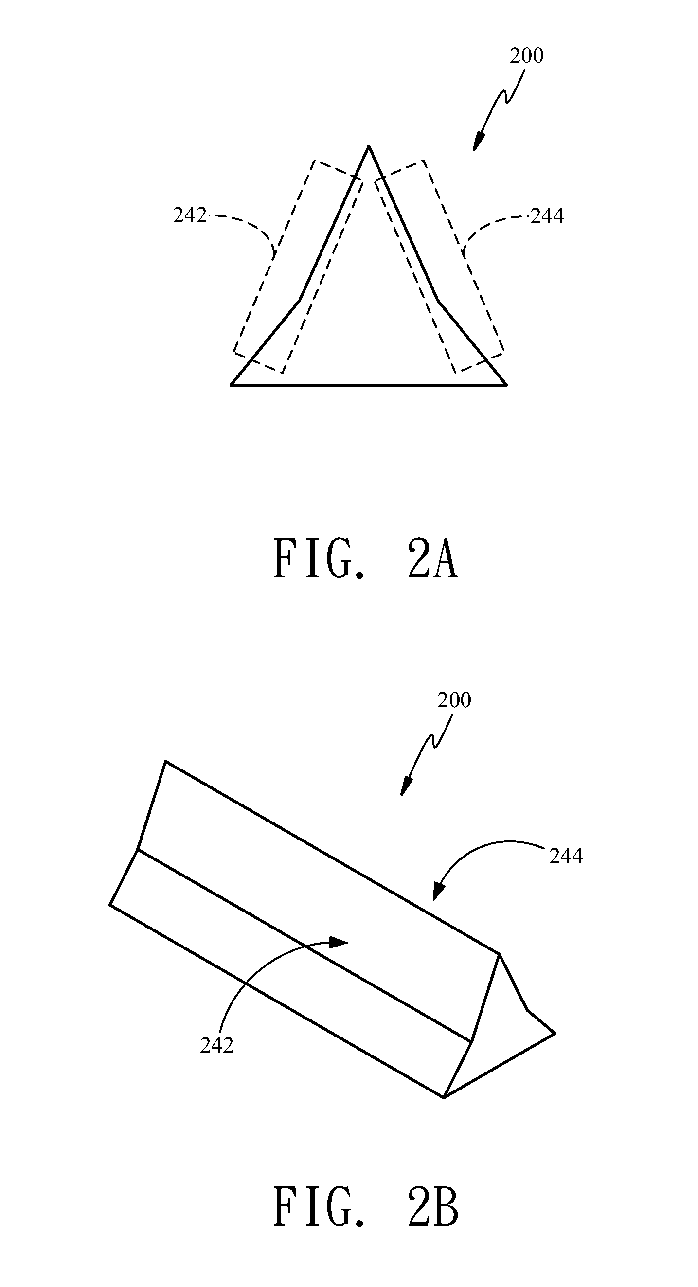
[0027]Referring to FIGS. 2A-2D, a reflecting device 200 according to the invention comprises a first surface 242 and a second surface 244. The first surface 242 and the second surface 244 are provided separately on the two sides, opposing to each other, of the reflecting device 200. At least one of the first surface 242 and the second surface 244 comprises at least two planes. In the at least two planes, every two planes are connected with an included angle more than 90 degrees and less than 180 degrees. FIG. 2A is a cross-sectional schematic diagram of the reflecting device 200 comprising the first surface and the second surface, each having two planes. FIG. 2C is a cross-sectional schematic diagram of the reflecting device 200 comprising the first surface and the second surface, each having three planes. FIG. 2B and FIG. 2D are three-dimensional schematic diagrams of FIG. 2A and FIG. 2C, respectively. In addition, one of the first surface 242 and the second surface 244 or combination thereof can be made of material having a reflecting or scattering property. The reflecting device 200 can be applied in a direct type LED backlight unit or direct type CCFL backlight unit as well as a LED lighting apparatus to enhance the brightness of a lighting device.
[0028]FIGS. 3A and 3B show the top view and side view of a backlight unit 300 having a reflecting device for light directivity enhancement according to the present invention. The backlight unit 300 comprises a light source module 320, comprising at least one light source 322, and a reflecting device 340. The reflecting device 340 is provided to surround the light source 322, as shown in FIG. 3A or to surround the light source module 320, as shown in FIG. 3C. The reflecting device 340 comprises a first surface 342 and a second surface 344. The first surface 342 and the second surface 344 are provided separately on the two sides, opposing to each other, of the reflecting device 300. At least one of the first surface 342 and the second surface 344 comprises at least two planes. In the at least two planes, every two planes are connected with an included angle more than 90 degrees and less than 180 degrees.
[0029]In one embodiment, as shown in FIG. 3B, the at least two planes of the first surface 342 and the at least two planes of the second surface 344 form a concave surface, the concave surface has a notch facing toward the light source 322, and a second concave surface of the other light source 323, respectively. The first concave surface reflects the light side-emitted from the light source 322 to direct the light toward the vertical direction of the light source 322, referring to the light path shown by the dotted line in FIG. 3B. The second concave surface reflects the light side-emitted from the other light source 323 to direct the light toward the vertical direction of the light source323. In addition, one of the first surface 342 and the second surface 344 or combination thereof can be made of material having a reflecting or scattering property. Besides, the light source module 320 has a direct type LED light source structure. The LED light source is a side emitting LED. For example, the LED light source is the Luxeon® III product made by Lumileds. In addition, the reflecting device 340 surrounds one single LED light source 322 or surrounds the light source module 320 to form a circle (FIG. 3D shows a schematic diagram illustrating the reflecting device 340 surrounding one single LED light source), square (as shown in FIG. 3E), ellipse (as shown in FIG. 3F), parallelogram, or any other polygon.
[0030]In another embodiment, the backlight unit 300 can be applied in adaptive dimming technique and the reflecting device 340 is an optical isolator in the adaptive dimming technique. The so-called adaptive dimming technique is to lower power consumption and enhance picture contrast by controlling the brightness variation of the backlight unit in different areas with different levels. The adaptive dimming technique can be categorized into three classes: zero dimensional (OD), one dimensional (1D), two-dimensional (2D) dimming, the corresponding light sources of which are plane light source (Electro Luminescence and organic light emitting diode), CCFL (or external electrode fluorescent lamp (EEFL) similar to CCFL), and light emitting diode (LED). The reason of using a LED as a light source in a backlight unit is that the backlight unit can be divided into the most quantities of effective control areas so as to fine adjust picture contrast.
[0031]In order to control the brightness of different areas, the backlight unit has to be divided into small blocks, which are accomplished by an optical isolator. As shown in FIG. 4, an optical isolator 410 in the traditional adaptive dimming technique is a thin isolating plate. Generally, the thin isolating plate surrounds one single light source or a plurality of light sources to form a rectangular matrix. The traditional optical isolator 410 is not designed to have any additional optical property and is only used to block side-emitting light that is emitted by the light source within a certain area to prevent the side-emitting light from interfering the brightness control of the other area. Therefore, the reflecting device 340 is used as an optical isolator in this embodiment to control the directivity of the light emitted from the light source 322 for enhancing the brightness of the backlight unit, besides the original purpose and function of an optical isolator.
[0032]In another embodiment, the light source module 300 has a cold cathode fluorescent lamp (CCFL) light source structure and the reflecting device 340 surrounds the two sides of the CCFL 324 or the two sides of the light source module. FIG. 3G shows a cross-sectional diagram illustrating the reflecting device surrounding the two sides of one single cold cathode fluorescent lamp (CCFL) while FIG. 3H is a three-dimensional schematic diagram of FIG. 3G.
[0033]Besides, the above mentioned backlight unit 300 may comprise one of the followings or combination thereof: a diffusing film and a brightness enhancement film (BEF).
[0034]On the other hand, as the reflecting device according to the invention is applied in a 22 inch direct type backlight unit with a thickness of 20 mm, the backlight unit has brightness uniformity of 83% and an axial brightness gain of 87.18%.
[0035]The present invention provides a method for enhancing light directivity of a backlight unit in a liquid crystal display (LCD), comprising: providing a direct type light source module that comprises at least one light source; and providing a reflecting device that surrounds the light source or the light source module to reflect light emitted from the light source and direct the light toward a same direction. In addition, the reflecting device comprises a first surface and a second surface. The first surface and the second surface are provided separately on the two sides, opposing to each other, of the reflecting device. At least one of the first surface and the second surface comprises at least two planes. In the at least two planes, every two planes are connected with an included angle more than 90 degrees and less than 180 degrees.
[0036]The present invention provides a method for enhancing light directivity of a lighting apparatus, comprising: providing a light source module that comprises at least one light emitter; and providing a reflecting device that surrounds the light emitter or the light source module to reflect light emitted from the light emitter and direct the light toward a same direction. In addition, the reflecting device comprises a first surface and a second surface. The first surface and the second surface are provided separately on the two sides, opposing to each other, of the reflecting device. At least one of the first surface and the second surface comprises at least two planes. In the at least two planes, every two planes are connected with an included angle more than 90 degrees and less than 180 degrees. The lighting apparatus can be, for example, a car light, a street light, or a flashlight.
[0037]Obviously many modifications and variations are possible in light of the above teachings. It is therefore to be understood that within the scope of the appended claims the present invention can be practiced otherwise than as specifically described herein. Although specific embodiments have been illustrated and described herein, it is obvious to those skilled in the art that many modifications of the present invention may be made without departing from what is intended to be limited solely by the appended claims.

PUM

no PUM

Description & Claims & Application Information

We can also present the details of the Description, Claims and Application information to help users get a comprehensive understanding of the technical details of the patent, such as background art, summary of invention, brief description of drawings, description of embodiments, and other original content. On the other hand, users can also determine the specific scope of protection of the technology through the list of claims; as well as understand the changes in the life cycle of the technology with the presentation of the patent timeline. Login to view more.

Similar technology patents

Air-cooled thermal management for a fuel cell stack

ActiveUS8168344B2decrease thicknesslimit scope
Owner:HYAXIOM INC

Rear projection display device

InactiveUS20080024737A1increase in sizedecrease thickness
Owner:SONY CORP

Intraocular lens adapted for adjustment via laser after implantation

InactiveUS20050182489A1improved optical performance
Owner:MINU

Wide-angle optical system for solid-state image pickup device

InactiveUS20070146899A1secure back focus distanceimproved optical performance
Owner:ENPLAS

Display device

InactiveUS20170276990A1improved optical performance
Owner:INNOLUX CORP

Toilet seat

InactiveUS20160029860A1decrease thickness
Owner:RANFT DONALD

Aspheric lens structures and fabrication methods thereof

ActiveUS20080198481A1improved optical performance
Owner:VISERA TECH CO LTD +1

Soft power wireless transmission induction plate

InactiveUS20150102682A1decrease thickness
Owner:COREMATE TECH CO LTD

Circuit adapter board

ActiveUS20190187182A1decrease thicknessdecrease height
Owner:WU HSIN LUNG

Classification and recommendation of technical efficacy words

  • improved optical performance

Intraocular lens adapted for adjustment via laser after implantation

InactiveUS20050182489A1improved optical performance
Owner:MINU

Aspheric lens structures and fabrication methods thereof

ActiveUS20080198481A1improved optical performance
Owner:VISERA TECH CO LTD +1

Display device

InactiveUS20170276990A1improved optical performance
Owner:INNOLUX CORP

Wide-angle optical system for solid-state image pickup device

InactiveUS20070146899A1secure back focus distanceimproved optical performance
Owner:ENPLAS
Why Eureka
Try Eureka