Aspheric lens structures and fabrication methods thereof

Active Publication Date: 2008-08-21
VISERA TECH CO LTD +1
6 Cites 8 Cited by

AI-Extracted Technical Summary

Problems solved by technology

Aspheric lenses have some optical advantages, but cannot be easily produced by traditional glass grinding and polishing techniques.
Aspheric lenses with all glass elements may be large and excessively expensive for use in compact digital cameras or accessories built into a cellular phone.
While molded plastic elements are inexpensive to produce, the level of precisi...

Method used

[0030]The invention is advantageous in that aspheric lens structures with dual aspheric surfaces on a plate are fabricated by lithography. The radius of curvature and surface profile of the aspheric lens structure can be precisely adjusted and controlle...

Benefits of technology

[0008]The invention is directed to aspheric lens structures with dual aspheric surfaces fabricated by ...

Abstract

Aspheric lens structures with dual aspheric surfaces and fabrication methods thereof are disclosed. An aspheric lens structure includes a first lens component with an aspheric top surface disposed on a second lens component, wherein the interface between the first lens component and the second lens component is spherical. The second lens component includes an aspheric back surface, wherein the radius of curvature of the aspheric top surface of the first lens component is different than the radius of curvature of the aspheric back surface of the second lens component. The second lens component may also include a planar back surface with a third lens component disposed on the planar back surface of the second component. The third lens component includes an aspheric back surface, wherein the radius of curvature of the aspheric top surface of the first lens component is different than the radius of curvature of the aspheric back surface of the third lens component.

Application Domain

Technology Topic

Aspheric lensOptoelectronics

Image

  • Aspheric lens structures and fabrication methods thereof
  • Aspheric lens structures and fabrication methods thereof
  • Aspheric lens structures and fabrication methods thereof

Examples

  • Experimental program(1)

Example

[0020]The following description is of the best-contemplated mode of carrying out the invention. This description is made for the purpose of illustrating the general principles of the invention and should not be taken in a limiting sense. The scope of the invention is best determined by reference to the appended claims.
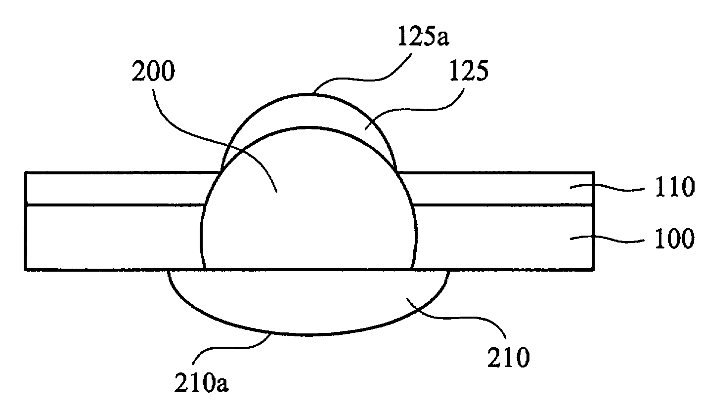
[0021]FIGS. 3-10 show cross sections illustrating fabrication of an exemplary embodiment of an aspheric lens structure with dual aspheric surfaces of the invention. Referring to FIG. 1, a substrate 100 is provided. Substrate 100 comprises a bulk silicon substrate, a quartz substrate or a glass substructure. Substrate 100 is configured as a carrier of the aspheric lens structure.
[0022]Referring to FIG. 4, the substrate 100 is perforated to create a through hole 105. The diameter of the through hole 105 is equal to or less than the diameter of a yet to be described ball lens. A ball lens 200 is inserted in the through hole 105 exposing a pre-curvature of the ball lens 200, as shown in FIG. 5.
[0023]Referring to FIG. 6, a layer of black dye 110 is applied to the substrate for obstructing an unnecessary part of the ball lens 200. The layer of black dye 110 is preferably formed by coating on the substrate 100 configured as a buffer for the aspheric lens structure.
[0024]Referring to FIG. 7. a photoresist layer 120 is conformably formed on the black dye layer 110 and the exposed ball lens 200. A mask 300 such as a phase transition mask is disposed over the main region corresponding to the aspheric lens. The phase transition mask includes a half tone mask or a gray tone mask. An aspheric lens component 125 with an aspheric surface 125a is formed on the ball lens 200 by forming a photoresist layer by lithography to serve as a first lens component as depicted in FIG. 8. The ball lens 200 is configured as a second lens component with a spherical back surface.
[0025]The preferable aspheric lens component 125 can optionally be heated and reflowed to change the radius of curvature of the aspheric surface 125a. Further, the aspheric lens component 125 can optionally be molded to change the curvature of the aspheric surface 125a.
[0026]Referring to FIG. 9, the back of the ball lens 200 is planarized to create a planar back surface. For example, chemical mechanical planarization (CMP) is performed to remove the convex back portion of the ball lens 200. A third lens component 210 with an aspheric back surface 210a is subsequently formed on the planar back surface of the ball lens 200, as depicted in FIG. 10. The third lens component 210 can be formed by molding. The radius of curvature of the aspheric top surface 125a of the first lens component 125 is different than the radius of curvature of the aspheric back surface 210a of the third lens component 210.
[0027]An array of aspheric lens structures with dual aspheric surfaces on a substrate can thus be fabricated by lithography. There are additional steps not mentioned here, which are required to complete the array of aspheric lens structures with dual aspheric surfaces, but which are not essential to an understanding of the invention.
[0028]FIGS. 11-12 are cross sections illustrating fabrication of another exemplary embodiment of an aspheric lens structure with dual aspheric surfaces of the invention. Referring to FIG. 11, the ball lens 200 is preferably composed of a UV dissolvable resin. The UV dissolvable ball lens 200 is irradiated by UV light and is removed by chemical solvent leaving a cavity.
[0029]Referring to FIG. 12, an alternative second lens component 250 with an aspheric back surface 250a is formed in the cavity. The alternative second lens component 250 can be formed by molding. The radius of curvature of the aspheric top surface 125a of the first lens component 125 is different than the radius of curvature of the aspheric back surface 250a of the alternative second lens component 250. Other steps not shown are undertaken to complete the aspheric lens structures with dual aspheric surfaces.
[0030]The invention is advantageous in that aspheric lens structures with dual aspheric surfaces on a plate are fabricated by lithography. The radius of curvature and surface profile of the aspheric lens structure can be precisely adjusted and controlled. The ability to mass produce aspheric lens structure arrays with dual aspheric surfaces on a plate can be achieved for wafer scale packaging. Optic performance, in comparison with conventional single aspheric surface lens plates, can also be improved.
[0031]While the invention has been described by way of example and in terms of the preferred embodiments, it is to be understood that the invention is not limited to the disclosed embodiments. To the contrary, it is intended to cover various modifications and similar arrangements (as would be apparent to those skilled in the art). Therefore, the scope of the appended claims should be accorded the broadest interpretation so as to encompass all such modifications and similar arrangements.

PUM

no PUM

Description & Claims & Application Information

We can also present the details of the Description, Claims and Application information to help users get a comprehensive understanding of the technical details of the patent, such as background art, summary of invention, brief description of drawings, description of embodiments, and other original content. On the other hand, users can also determine the specific scope of protection of the technology through the list of claims; as well as understand the changes in the life cycle of the technology with the presentation of the patent timeline. Login to view more.

Similar technology patents

Reflecting Device And Application thereof in Backlight Unit For Enhancing Light Directivity

InactiveUS20090316402A1Enhance light directivityImproved optical performanceNon-electric lightingPoint-like light sourcePhysicsDirectivity
Owner:CHUNG YUAN CHRISTIAN UNIVERSITY

Wide-angle optical system for solid-state image pickup device

InactiveUS20070146899A1Secure back focus distanceImproved optical performanceRecord information storageOptical beam guiding meansPhysicsDistortion
Owner:ENPLAS

Display device

InactiveUS20170276990A1Improved optical performanceNon-linear opticsElectrically conductiveEngineering
Owner:INNOLUX CORP

Classification and recommendation of technical efficacy words

Why Eureka
Try Eureka