

Wide-angle optical system for solid-state image pickup device
- Summary
- Abstract
- Description
- Claims
- Application Information
AI Technical Summary
Benefits of technology
Problems solved by technology
Method used
Image

Examples
examples
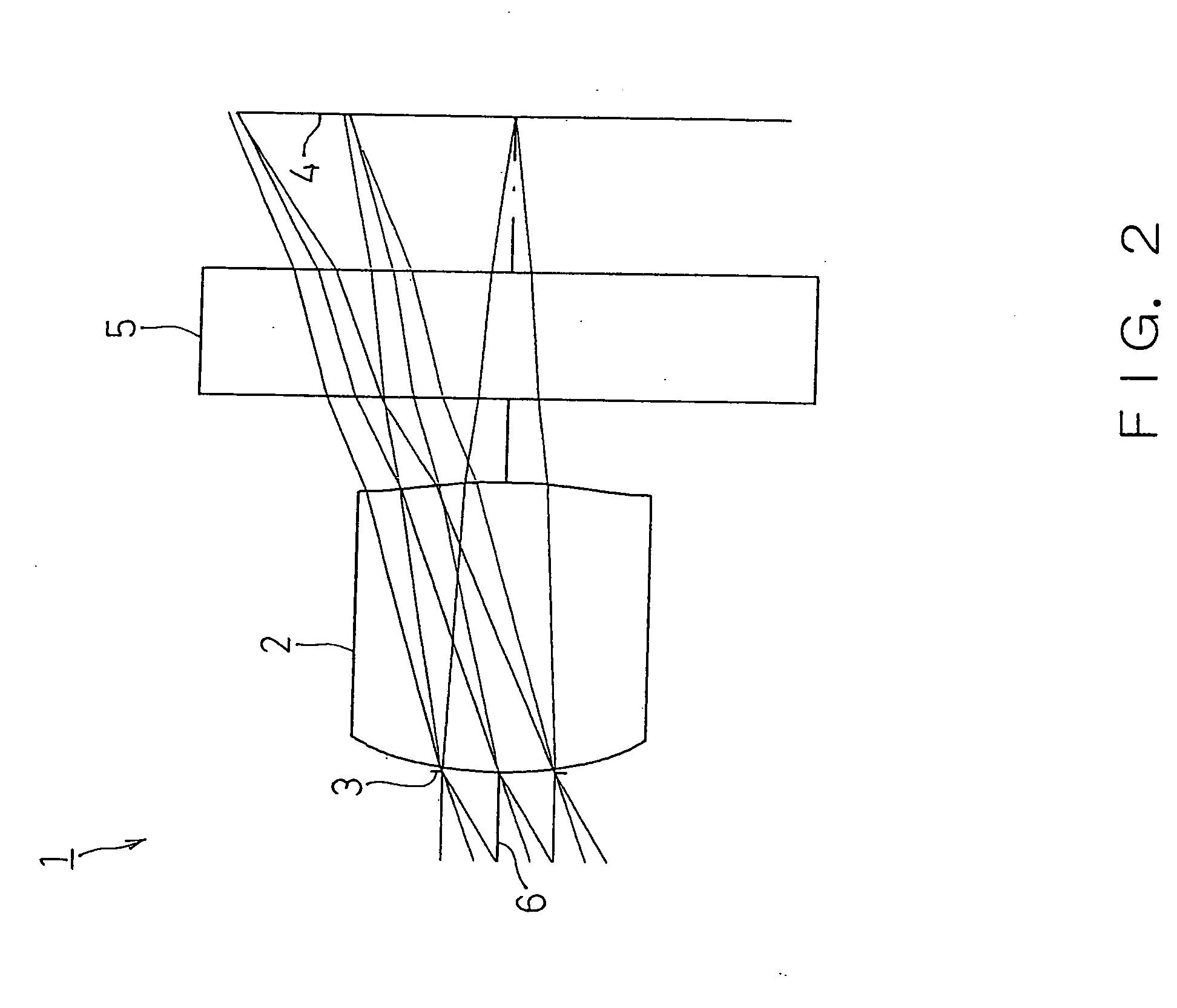
[0074] Next, EXAMPLES of the present invention will be described by referring to FIG. 2 or FIG. 7.
[0075] In the EXAMPLES, F no denotes F number and r denotes a curvature radius of an optical surface (the center radius curvature in the case of the imaging lens 2). In addition, d denotes a distance to the next optical surface. Further, 2ω denotes a total view angle (view angle of corresponding angles). Still further, nd denotes the index of refraction of each optical system when to the d line (yellow) is irradiated, and νd denotes the Abbe number of each optical system when the d line is similarly irradiated.
[0076] k, A, B, C, and D denote each coefficient in a following expression (6). Specifically, the shape of the aspherical surface of the imaging lens 2 is expressed by the following expression provided that the direction of the optical axis 6 is taken as the Z axis, the direction orthogonal to the optical axis 6 as the X axis, the traveling direction of light is positive, k is t...
first example
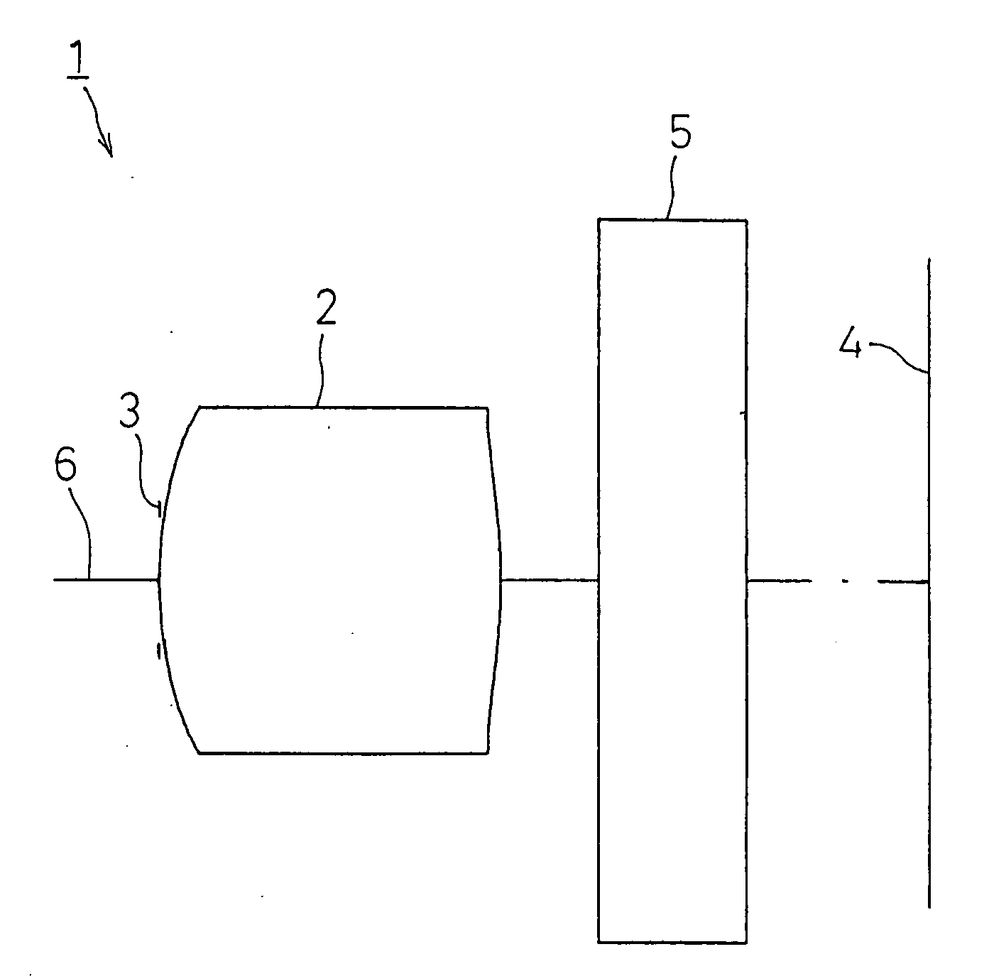
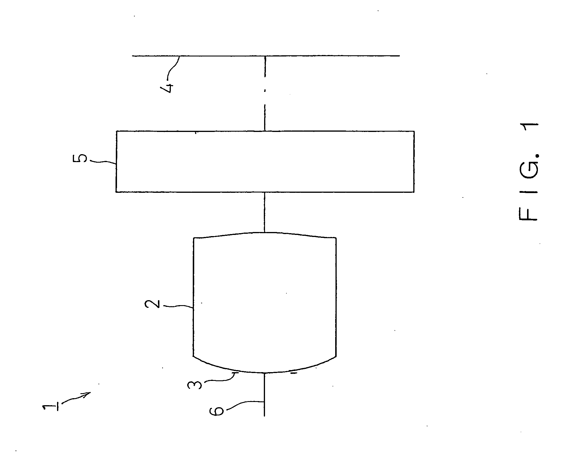
[0078]FIG. 2 shows a FIRST EXAMPLE of the present invention. In the FIRST EXAMPLE, like the wide-angle optical system for a solid image pickup device 1 with the structure of FIG. 1, the diaphragm 3 is disposed on the object side of the imaging lens 2 and a cover glass is disposed on the image surface side a the filter 5.
[0079] The wide-angle optical system for a solid image pickup device 1 of the FIRST EXAMPLE was set under the following condition.
Lens Data
[0080] f=1.064 mm, F no=4.0, 2ω=65°
Face Number (Object Point)rdndνd1(Diaphragm)0.0000.052(First Face of Imaging Lens)0.8700.701.53356.03(Second Face of Imaging Lens)−1.1760.204(First Face of Cover Glass)0.0000.301.51864.05(Second Face of Cover Glass)0.0006(Image Surface)
[0081]
Face NumberkABCD2 7.50E−1−1.09E−1−8.611.42E+2−2.41E+23−2.80E−11.601.00−1.502.00
[0082] Under such conditions, |r1 / r2|=0.74 was achieved, thereby satisfying the expression (1). d / fl=0.66 was achieved, thereby satisfying the expression (2). |r1 / fl|=1.11 was ...
second example
[0085]FIG. 4 shows a SECOND EXAMPLE of the present invention. In the SECOND EXAMPLE, like the wide-angle optical system for a solid image pickup device 1 with the structure of FIG. 1, the diaphragm 3 is disposed on the object side of the imaging lens 2 and a cover glass is disposed on the image surface side a the filter 5.
[0086] The wide-angle optical system for a solid image pickup device 1 of the SECOND EXAMPLE was set under the following condition.
Lens Data
[0087] f=1.052 mm, F no=4.0, 2ω=65°
Face Number (Object Point)rdndνd1(Diaphragm)0.0000.052(First Face of Imaging Lens)0.8330.651.53356.03(Second Face of Imaging Lens)−1.2500.204(First Face of Cover Glass)0.0000.301.51864.05(Second Face of Cover Glass)0.0006(Image Surface)
[0088]
Face NumberkABCD2 7.50E−1−1.09E−1−8.601.42E+2−2.41E+33−2.80E−11.851.00−1.502.00
[0089] Under such conditions, |r1 / r2|=0.67 was achieved, thereby satisfying the expression (1). d / fl=0.62 was achieved, thereby satisfying the expression (2). |r1 / fl|=1.19 w...
PUM
 Abstract
Description
Claims
Application Information