Screw structure with stop ring

a technology of screw structure and stop ring, which is applied in the direction of fastening means, fastener tools, electrical equipment, etc., can solve the problems of flange , /b> tending to be incompletely fitted in the through hole, poor packaging or even a damaged pcb b>7, etc., to achieve stably sucked, easy but accurate positioning, and without the risk of swaying easily

Active Publication Date: 2009-12-24
DTECH PRECISION INDS
View PDF12 Cites 4 Cited by
  • Summary
  • Abstract
  • Description
  • Claims
  • Application Information

AI Technical Summary

Benefits of technology

[0009]A primary object of the present invention is to provide a screw structure with a stop ring, so that the screw structure can be packaged to have a fixed height. That is, every component of the screw structure are restricted to a fixed position, allowing the screw structure to have a fixed center of gravity without the risk of swaying easily. Therefore, the screw structure can be stably sucked with a sucking tool and then easily but accurately positioned on a PCB without becoming deviated and skewed.

Problems solved by technology

(a) When assembling the screw 5 to the PCB 7, the ferrule 53 is directly aligned with the through hole 71. However, since the head 51 and the ferrule 53 could not be held together through compression during assembling, the ferrule 53 and the head 51 tend to move relative to each other due to the small clearance existed between them. As a result, the ferrule 53 is frequently misaligned with the through hole 71.
(b) Since the screw 5 is very small in volume and the through hole 71 has a relatively small diameter, the alignment of the flange 531 on the ferrule 53 of the screw 5 with the through hole 71 is easily subject to error, preventing the flange 531 on the ferrule 53 from being successfully aligned with the through hole 71 and resulting in a poorly packaged or even a damaged PCB 7.
(c) In the event the flange 531 of the ferrule 53 is not pressed into the through hole 71 in one single operation, the flange 531 tends to be incompletely fitted in the through holes 71 and become deviated or skewed due to inaccurate planeness of the PCB 7.
(d) To assemble the screw 5 to the PCB 7 by pressing the toothed flanges 531 of the ferrules 53 into the through holes 71, the screw 5 is individually fetched to the PCB 7. Therefore, the assembly of a large amount of screws 5 to the PCB 7 could not be efficiently carried out using the surface mount technology (SMT) that has been widely employed in the electronic industrial field.

Method used


Image

  • Screw structure with stop ring
  • Screw structure with stop ring
  • Screw structure with stop ring

Examples


Embodiment Construction

[0024]Before describing the screw structure of the present invention in details, a manner of assembling the screw structure to a printed circuit board (PCB) is explained first. Please refer to FIG. 6 that is a flowchart showing the steps of assembling the screw structure of the present invention to a PCB. As shown, the assembling steps include:

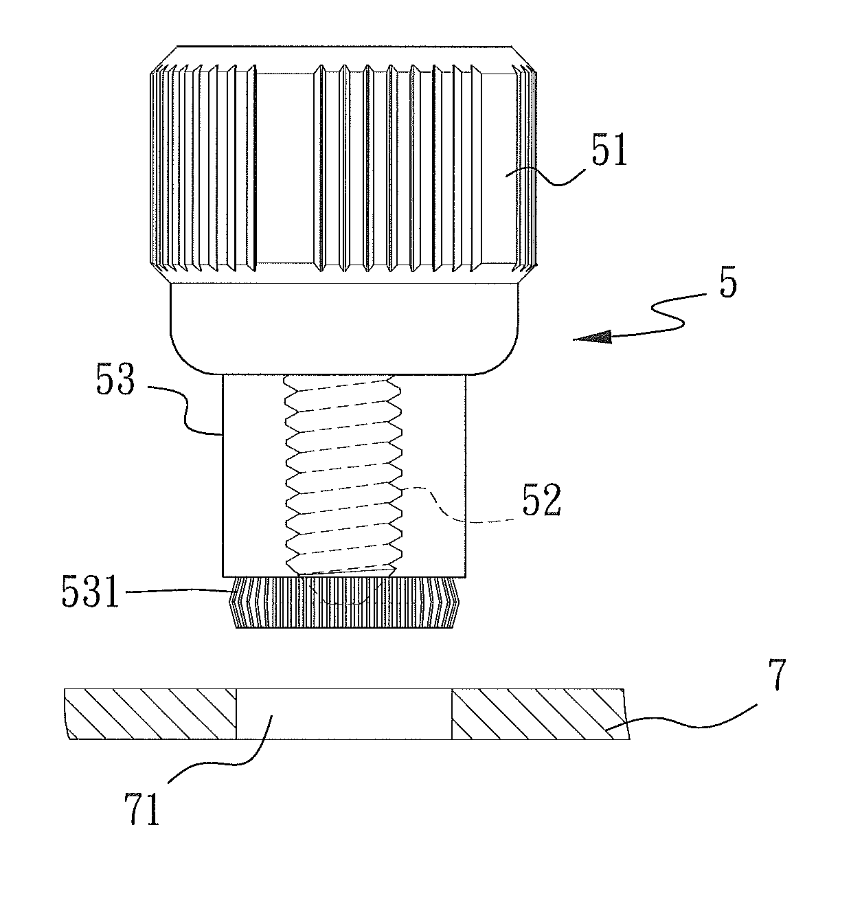
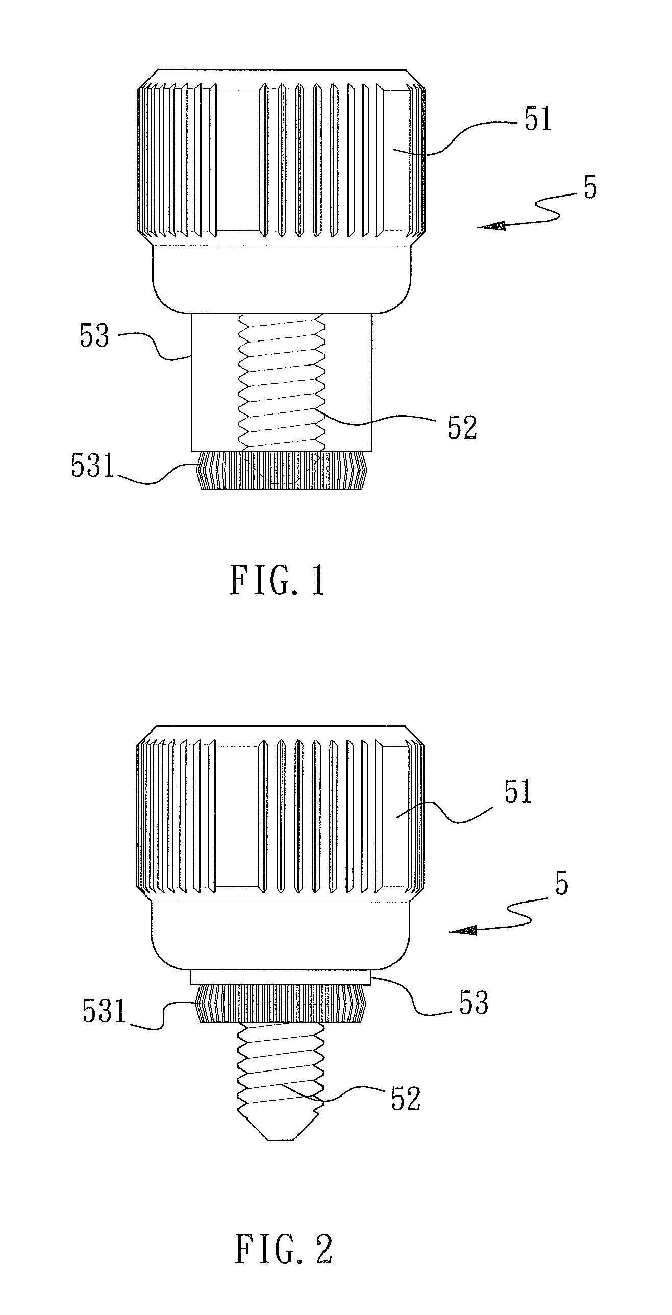
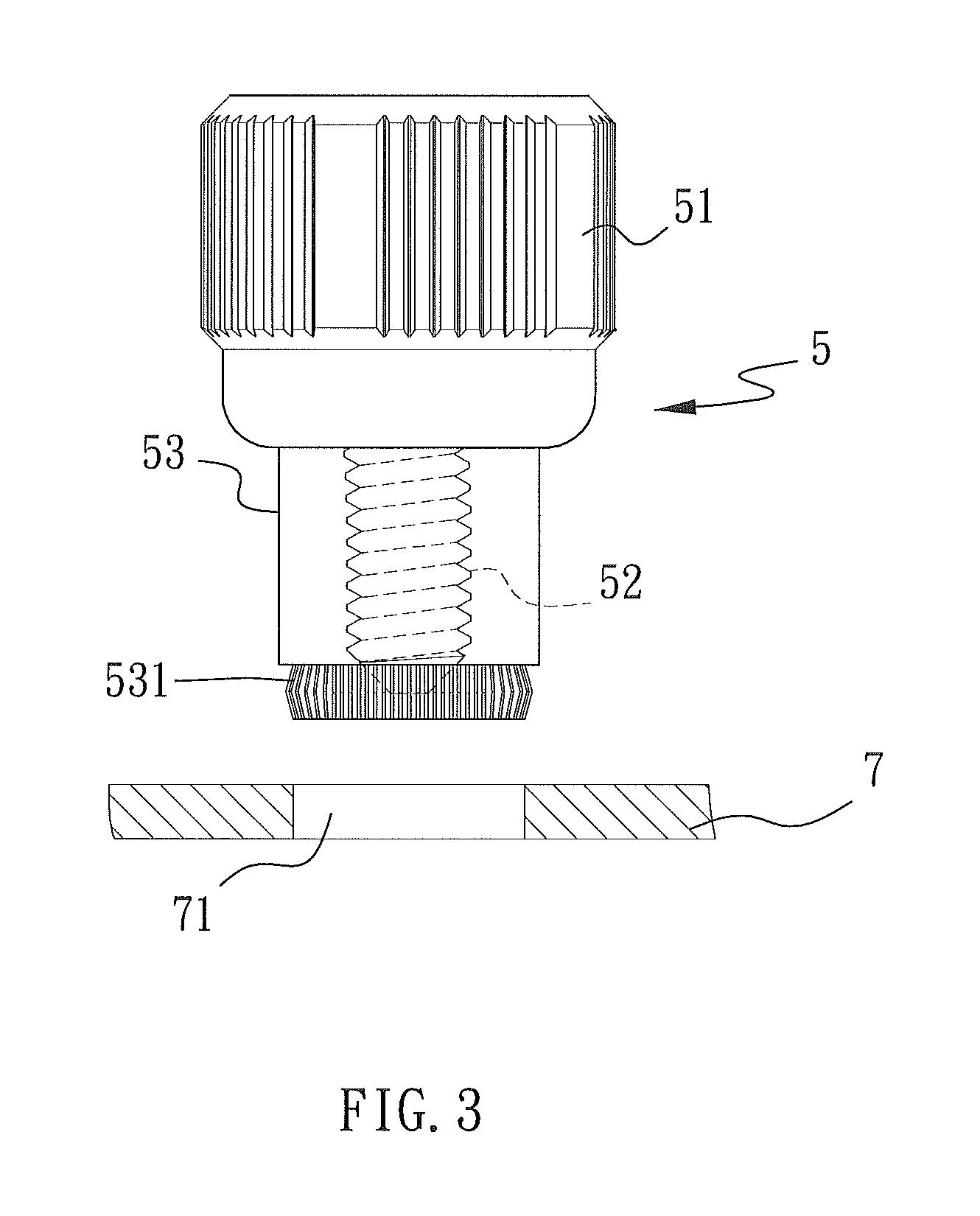
[0025](1) Providing a screw structure. As can be seen in FIGS. 7A and 7B, the screw 1 includes a head 11 and a threaded shank 12 forward extended and projected from an inner side of the head 11, and a ferrule 13 enclosing the threaded shank 12. And, in a preferred embodiment, the screw structure further includes a spring 15 having an end pressed against the inner side of the head 11 and another end pressed against a rear end of the ferrule 13. With the spring 15, the ferrule 13 is elastically retractable into or extendable from the head 11.

[0026](2) Fitting a stop ring 14 on the threaded shank 12 to press against a front end of the ferrule 13,...


PUM


Abstract

A screw structure with a stop ring includes a screw, a ferrule, and a stop ring. The stop ring is fitted on a threaded shank of the screw to push against a front end of the ferrule, so that the ferrule is pressed against a head of the screw. With the ferrule being firmly pressed against the head of the screw by the stop ring, the ferrule will not sway relative to the screw, allowing the screw structure to be stably sucked with a sucking tool and be highly accurately assembled to a printed circuit board.

Description

CROSS-REFERENCE TO RELATED APPLICATIONS[0001]This application is a continuation-in-part patent application of U.S. application Ser. No. 12 / 032,748 filed on 18 Feb. 2008, the entire contents of which are hereby incorporated by reference for which priority is claimed under 35 U.S.C. § 120.FIELD OF THE INVENTION[0002]The present invention relates to a screw structure, and more particularly to a screw structure with a stop ring that provides enhanced stability during the process of assembling the screw structure to a printed circuit board (PCB).BACKGROUND OF THE INVENTION[0003]FIG. 1 shows a conventional screw for using with a printed circuit board (PCB). The screw 5 includes a head 51, a threaded shank 52, and a ferrule 53 having a free end with an axially extended toothed flange 531. The ferrule 53 normally encloses the threaded shank 52 and is retractable into the head 51 under pressure to expose the threaded shank 52, as shown in FIG. 2. To assemble the screw 5 to a PCB 7, first ali...

Claims


Application Information

Patent Timeline
Patent Type & Authority Applications(United States)
IPC IPC(8): F16B21/18
CPCH02G3/0691F16B5/0208Y10S411/999
Inventor WANG, TING-JUI
Owner DTECH PRECISION INDS
Why Eureka
Try Eureka