
Method of improving a dehydrogenation process

a dehydrogenation process and process technology, applied in the direction of organic chemistry, chemistry apparatus and processes, hydrocarbon preparation catalysts, etc., can solve the problems of decreased catalyst bed production and decreased run length, and achieve the effect of improving the dehydrogenation process and reducing the decline ra

Inactive Publication Date: 2009-12-24
SHELL OIL CO
View PDF22 Cites 11 Cited by
  • Summary
  • Abstract
  • Description
  • Claims
  • Application Information

AI Technical Summary

Benefits of technology

The invention provides a method for improving a dehydrogenation process by replacing a portion of a dehydrogenation catalyst with an inert material and introducing a feed comprising a dehydrogenatable hydrocarbon into the reactor wherein the feed entering the reactor contacts the catalyst before contacting the inert material. This method results in a lower pressure drop across the catalyst and a higher conversion of the dehydrogenatable hydrocarbon. Additionally, the invention provides a method of dehydrogenation of a dehydrogenatable hydrocarbon in a radial reactor where a first catalyst was previously removed and a second catalyst was loaded, where the second catalyst has a lower decline rate than the first catalyst and the volume of the second catalyst is at most 90% of the volume of the first catalyst. This method also results in higher conversion of the dehydrogenatable hydrocarbon.

Problems solved by technology

The thin beds contain less catalyst, which results in decreased production of the catalyst bed.
In addition, the catalyst deactivates over time and operating a reactor with less catalyst results in a decreased run length.

Method used


Image

  • Method of improving a dehydrogenation process
  • Method of improving a dehydrogenation process
  • Method of improving a dehydrogenation process

Examples


example 3

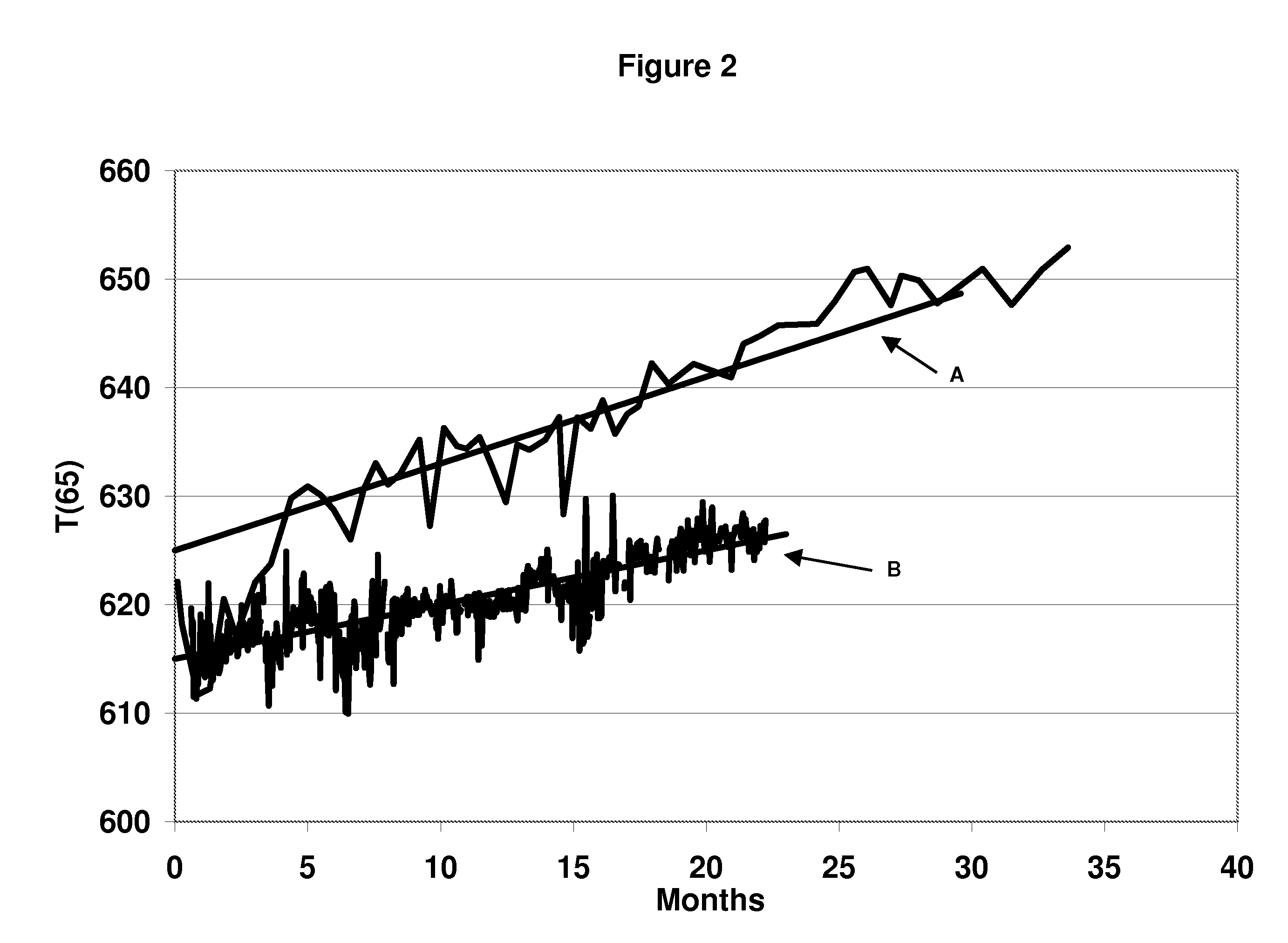
[0069]This example calculates the inlet temperature of the reactor at 3 months and at 24 months to maintain a constant 65% conversion for the reactor of Example 1 wherein the total volume of conventional catalyst is removed and the reactor is 75% filled with the same low decline rate catalyst described in Example 2. That means that the volume of catalyst in this reactor is 75% of the volume of catalyst used in Examples 1 and 2. All process variables besides temperature were the same as in Example 1. The results are shown in Table 1 and show that there is still some remaining catalyst activity at 24 months.

example 4

[0070]This example calculates the inlet temperature of the reactor at 3 months and at 24 months to maintain a constant 65% conversion for the reactor of Example 1 wherein the total volume of conventional catalyst is removed and the reactor is 50% filled with the same low decline rate catalyst described in Example 2. All process variables besides temperature were the same as in Example 1. The results are shown in Table 1 and show that the reactor has reached end of run conditions.

[0071]As can be seen from these examples, it is possible to achieve the same run length of 24 months using a reactor full of conventional catalyst or a reactor 50% full with low decline rate catalyst. Alternatively, the reactors in Examples 2 and 3 could be operated for longer than 24 month run lengths before the inlet temperature reached the maximum of 650° C. The higher inlet temperatures at 3 months for Examples 3 and 4 are required to compensate for higher liquid hourly space velocity.

TABLE 1DeclineCatal...


PUM

PropertyMeasurementUnit
thicknessaaaaaaaaaa
thicknessaaaaaaaaaa
thicknessaaaaaaaaaa

Abstract

The invention relates to a method of improving a dehydrogenation process comprising: removing a volume of a first dehydrogenation catalyst from a radial dehydrogenation reactor; loading the reactor with a volume of a second dehydrogenation catalyst that has a lower decline rate than the first dehydrogenation catalyst; and passing a dehydrogenatable hydrocarbon through the reactor wherein the volume of the second catalyst is at most 90% of the volume of the removed catalyst.

Description

[0001]This application claims the benefit of U.S. Provisional Application No. 61 / 043,419, filed Apr. 9, 2008, which is hereby incorporated by reference.FIELD OF THE INVENTION[0002]The invention relates to a method of improving a dehydrogenation process.BACKGROUND[0003]There have been continuous efforts to improve the efficiency of dehydrogenation process systems. One of the important objectives is ensuring the catalyst is removed after an optimal run length. If it is removed before the optimal run length then the catalyst will have remaining activity that is not used. If the catalyst is removed after the optimal run length then the system is operated at a less than optimal conversion for some time. In most instances, the run length is determined by external factors, so the objective becomes maximizing the use of the catalyst during that run length.[0004]U.S. Patent Application Publication 2002 / 0065442 describes a method for improving a dehydrogenation process system performance. It ...

Claims


Application Information

Patent Timeline
Patent Type & Authority Applications(United States)
IPC IPC(8): C07C5/32
CPCC07B35/04C07C5/333C07C5/3332C07C2523/745C07C15/46
Inventor NEWMAN, RICHARD DOUGLAS
Owner SHELL OIL CO
Learn More