[0012]The interference bodies are preferably radiopaque and ductile. Radiopacity allows for radiologic
visualization of the
implant during and after device deployment by use of the attachment bodies alone. Especially when serving dual-use as marker plus attachement features, the bodies will typically be set at or adjacent (at least) the ends of the graft and / or stent. However, they may be used at any suitable location on the device.
Ductility of the interference members allows them to conform around any receptacle features provided to enhance interference and / or slightly “
mushroom” or “head” along an inner periphery of the receptacle. The strength offer by
metal bodies so-processed may be desirable. However, polymeric bodies may be similarly employed in forming an
interference fit to retain the graft.
[0015]Post-deployment retention of the
polymer blocks within the stent may not however, be necessary as the
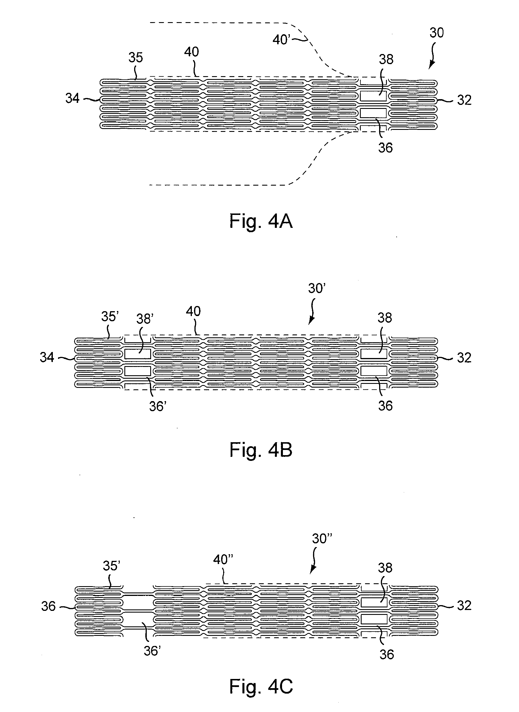
apposition of the stent graft in the vessel upon implantation is often sufficient to retain the positions of both the stent and graft. As such, another variation of the invention employs only temporary retention of the attachment bodies. As such, the stent cells themselves may suffice as temporary receptacles for the
polymer members, thereby eliminating the need to form designated eyelets within the stent lattice. When the stent is compressed, the cells can form interstices or pockets to retain the bonding bodies until the stent geometry changes shape upon stent expansion.
[0018]With the various approaches to graft retention described herein, at least one distal graft connection point is employed. More typically, a plurality of connection points, regions or sections are utilized, often around a circumference of the stent. Both proximal and distal connection points are advantageously employed so that neither end of the graft is prone to migration during advancement or retraction in achieving ideal placement. Moreover, medial connection points may also be employed. Such connection points may offer further stability / support to the graft. It is also contemplated that the graft may be secured to either the exterior or the interior of the stent, with attachment bodies applied accordingly.
[0023]In addition, while the interference / press-fit approach described usually makes reference to using
metal bodies, high-strength
polymer members can be used instead. A polymer such as PEEK can offer sufficient structural interface to retain position within the receptacle and hold the graft.
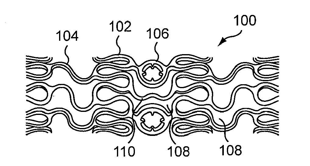
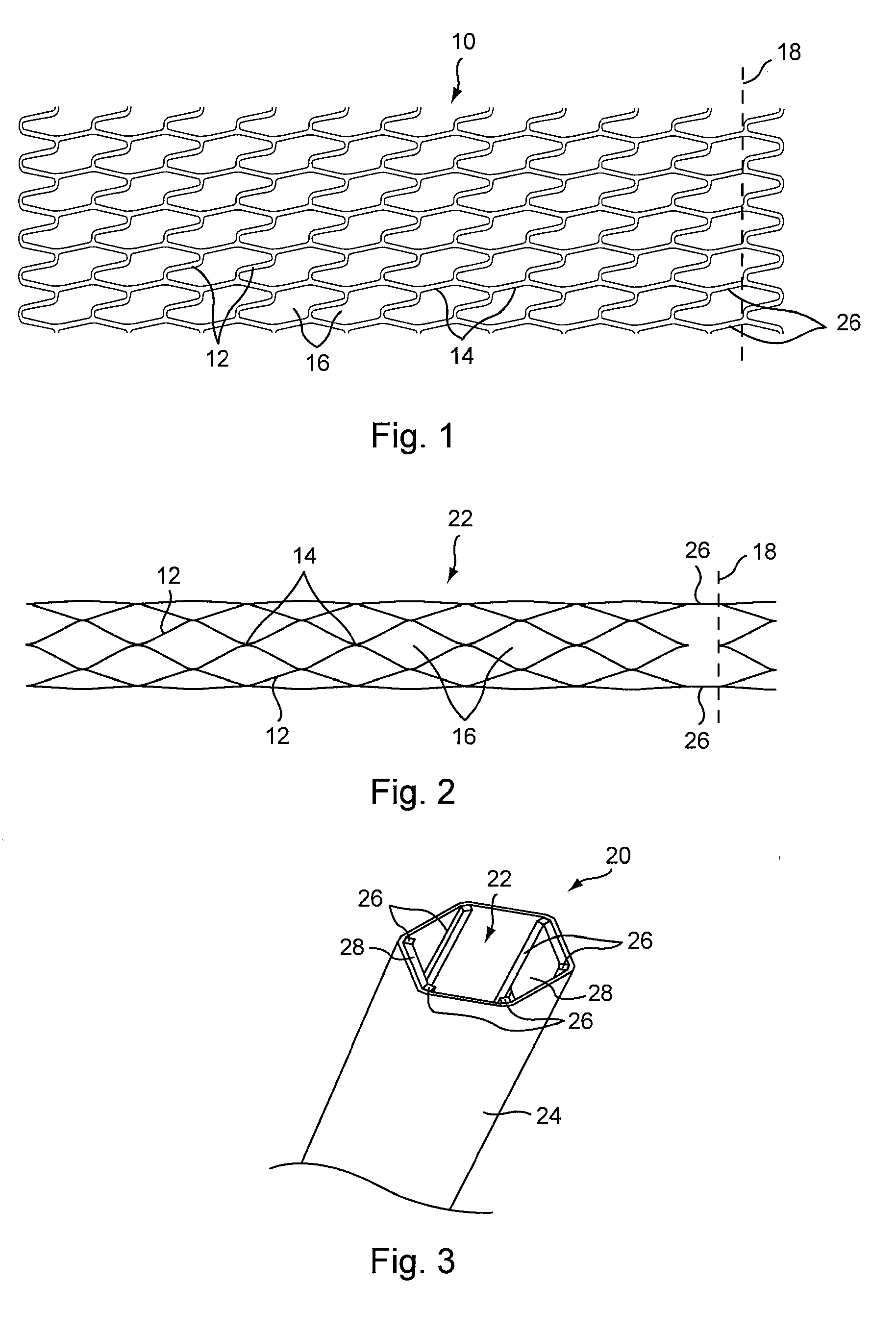
[0025]While any suitable stent pattern may be used with the graft retention features of the present invention, the invention also provides a unique stent lattice structure which is highly flexible when in a closed or compressed condition, yet provides superior support to the graft material when in an open or expanded condition. In a closed condition, the stent struts are highly curved, providing enhanced flexibility particularly along the longitudinal axis of the stent When open, the stent struts arrange themselves to provide repeating cells having a roughly
rhomboid shape. While the segments of the open rhombus structure are substantially identical in shape, they are not when the stent is closed or compressed. Rather, they are optimized for delivery trackability.
[0030]As with the other variations of the stent graft, in the practice of the method, the support structure or stent can be
balloon expandable, or self-expandable. For
balloon expanding embodiments, in one method of treatment, upon reaching an
aneurysm, the balloon is expanded to cause the stent to expand, often to its fullest capacity, and to stretch the graft tightly around the stent. The self-expanding stent grafts are delivered as is customary for self-expanding stents otherwise, (i.e., within a
catheter or delivery sheath). The graft material is folded around the crimped stent, and stent and graft are placed within the
catheter. Once the stent is placed at the
aneurysm (and released from the
catheter) the stent expands to stretch the graft material and fit snuggly at the site of the
aneurysm. Radiopaque features allow the practitioner to guide both types of stent into place.

