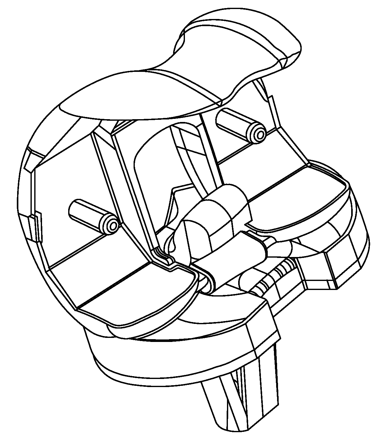
Total Knee Replacement Prosthesis With High Order NURBS Surfaces

a total knee and prosthesis technology, applied in the field of knee replacement prosthesis, can solve the problems of inability to accurately replicate the condylar surface inability to accurately replicate the natural motion path of the human knee, and inability to achieve simple designs

Active Publication Date: 2009-12-24
MAXX ORTHOPEDICS INC
View PDF60 Cites 116 Cited by
  • Summary
  • Abstract
  • Description
  • Claims
  • Application Information

AI Technical Summary

Benefits of technology

[0021]Another embodiment of the prosthesis is designed for use when the posterior cruciate ligament is retained. In this embodiment, the femoral component does not include the cam and the tibial component does not include the central post. Anterior and posterior translation of the femoral component relative to the tibial component, as well as tibial axial rotation, is controlled by the posterior cruciate ligament. The articular NURBS surfaces enable posterior femoral rotation and internal tibial rotation as the knee is flexed.

Problems solved by technology

Known total knee prostheses do not accurately replicate the condylar surfaces of the human knee.
Such simple designs have largely been abandoned because of high loosening rates associated with the high rotational stresses placed on the prosthetic components.
However, these prostheses do not accurately replicate the natural motion path of the human knee and have other manufacturing and durability limitations.
However, the complex motion path of the human knee can not be replicated using simple geometries.
Prostheses modeled using simple geometries produce unnatural motion, undue tension and pain in the ligaments, and increased wear and loosening of the prosthetic components.

Method used


Image

  • Total Knee Replacement Prosthesis With High Order NURBS Surfaces
  • Total Knee Replacement Prosthesis With High Order NURBS Surfaces
  • Total Knee Replacement Prosthesis With High Order NURBS Surfaces

Examples


Embodiment Construction

[0048]For the purpose of illustrating the invention, several embodiments of the invention are shown in the accompanying drawings. However, it should be understood by those of ordinary skill in the art that the invention is not limited to the precise arrangements and instrumentalities shown therein and described below. Throughout the specification, like reference numerals are used to designate like elements. Numerous changes and modifications within the spirit and scope of the invention will become apparent to those skilled in the art from this detailed description.

[0049]Unless otherwise defined, all technical and scientific terms used herein in their various grammatical forms have the same meaning as commonly understood by one of ordinary skill in the art to which this invention belongs. The terms anterior, posterior, proximal, distal, medial, lateral, sagittal, coronal, and transverse are used herein with their conventional medical / anatomical meaning as defined, for example, in Dor...


PUM


Abstract

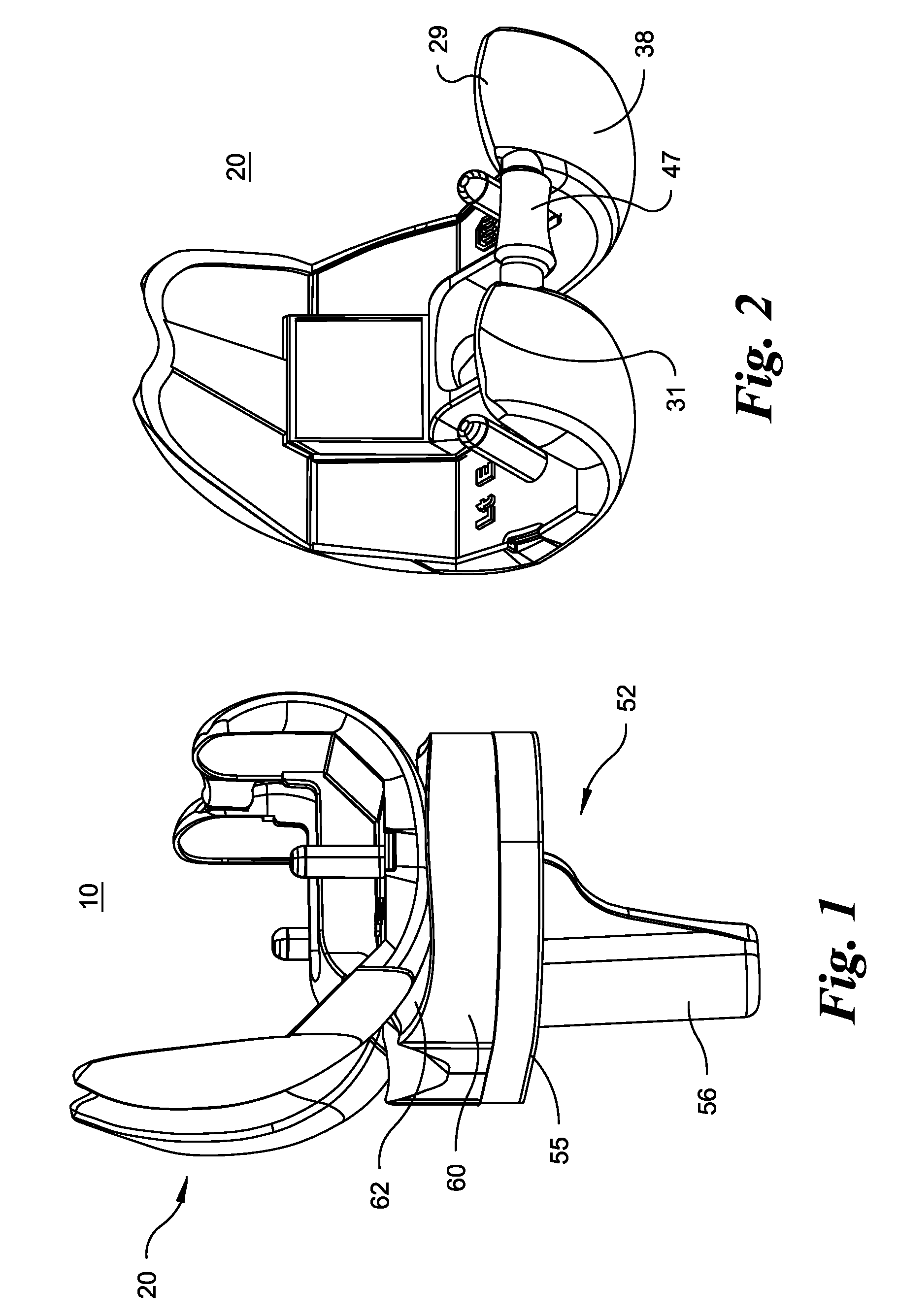
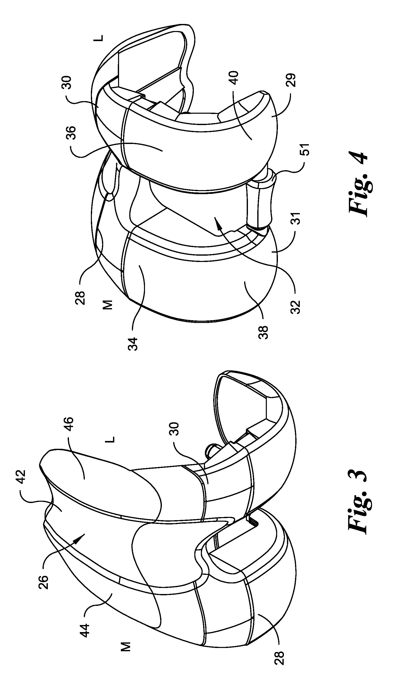
A knee replacement prosthesis comprising a femoral component and a tibial component that enable anterior-posterior translation of the femur relative to the tibia and enable the tibia to rotate about its longitudinal axis during flexion of the knee. The femoral component connects to the distal end of a resected femur and includes medial and lateral condyles having distal, articulating surfaces, and a patellar flange having a patellar articulating surface. The tibial component connects to the proximal end of a resected tibia and includes a proximal bearing surface with medial and lateral concavities that articulate with the medial and lateral condyles. The condylar articulating surfaces and the said concavities are substantially defined by non-uniform, rational B-spline surfaces (NURBS).

Description

RELATED APPLICATIONS[0001]This is a nonprovisional application claiming priority to U.S. provisional application No. 61 / 029,438 filed Feb. 18, 2008 entitled Total Knee Replacement Prosthesis with High Order NURBS Surfaces, incorporated herein by reference, and U.S. provisional application No. 61 / 029,457 filed Feb. 18, 2008 entitled Total Knee Replacement Prosthesis, incorporated herein by reference.FIELD OF THE INVENTION[0002]The present invention relates to a knee replacement prosthesis, in particular, a prosthetic knee implant having articulating surfaces defined by non-rational, uniform, B-spline surfaces (NURBS) that more accurately mimic the function and movement of the natural knee.BACKGROUND OF THE INVENTION[0003]While seemingly simple to the casual observer, the human knee articulates along a complex path. As the knee is flexed, the tibia obviously rotates (flexes) about a coronal axis relative to the femur. However, the femur also translates posteriorly on the tibia and the...

Claims


Application Information

Patent Timeline
Patent Type & Authority Applications(United States)
IPC IPC(8): A61F2/38
CPCA61F2/38A61F2/3886A61F2230/0065A61F2220/0025A61F2310/00029A61F2002/30518A61F2002/302A61F2/3094A61F2310/00023A61F2002/30878
Inventor SHAH, ASITJASTI, MURALI
Owner MAXX ORTHOPEDICS INC
Why Eureka
Try Eureka