Carpet cleaning wand having uniform air flow distribution

a technology of air flow distribution and carpet cleaning wand, which is applied in the field of carpet cleaning wands, can solve the problems of counterintuitive designs of both designs, and achieve the effects of uniform air flow distribution, increased flow area, and decreased flow resistan

Active Publication Date: 2009-12-31
HYDRAMASTER LLC
View PDF33 Cites 13 Cited by
  • Summary
  • Abstract
  • Description
  • Claims
  • Application Information

AI Technical Summary

Benefits of technology

[0009]The internal airfoil design interrupts the internal suction channel right along its centerline and diverts air flow towards the outside edges of the internal suction channel. The internal airfoil thus also effectively closes the center of the internal suction channel before allowing space for the air flow to equalize nearer the lips of the intake opening.
[0010]Another design includes the non-uniform cross section of the internal suction channel in combination with the internal airfoil along its centerline. This design utilizes the internal airfoil to interrupt the internal suction channel along its centerline and divert air flow towards its outside edges, while utilizing the pair of substantially symmetric elongated ovoids to increase flow area and gradually decrease flow resistance towards the outside edges of the wand. This combination of the two designs produces the most uniform air flow distribution at the lips of the intake opening.

Problems solved by technology

Both designs are counterintuitive since they utilize structure for interrupting the suction channel instead of keeping it open and unobstructed as is the accepted wisdom as practiced in the current state of the art.

Method used


Image

  • Carpet cleaning wand having uniform air flow distribution
  • Carpet cleaning wand having uniform air flow distribution
  • Carpet cleaning wand having uniform air flow distribution

Examples


Embodiment Construction

[0039]In the Figures, like numerals indicate like elements.

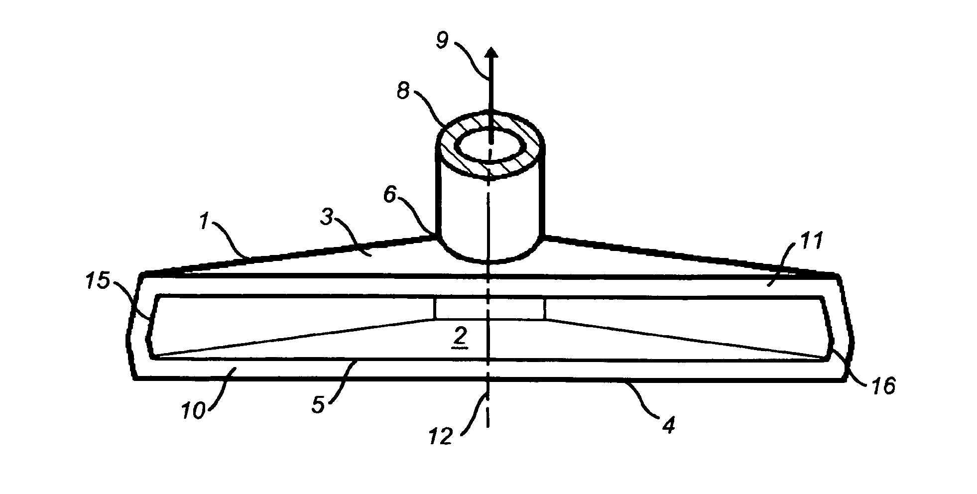
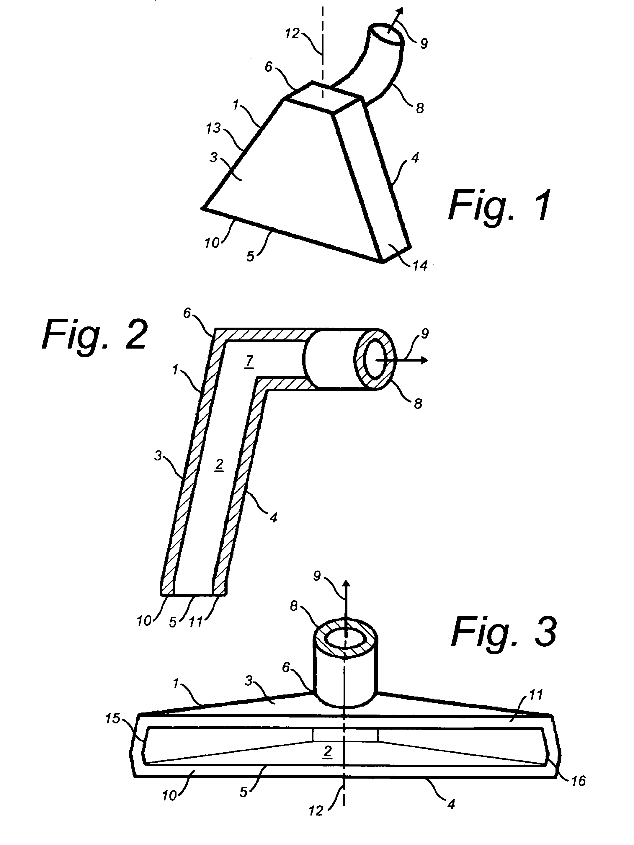
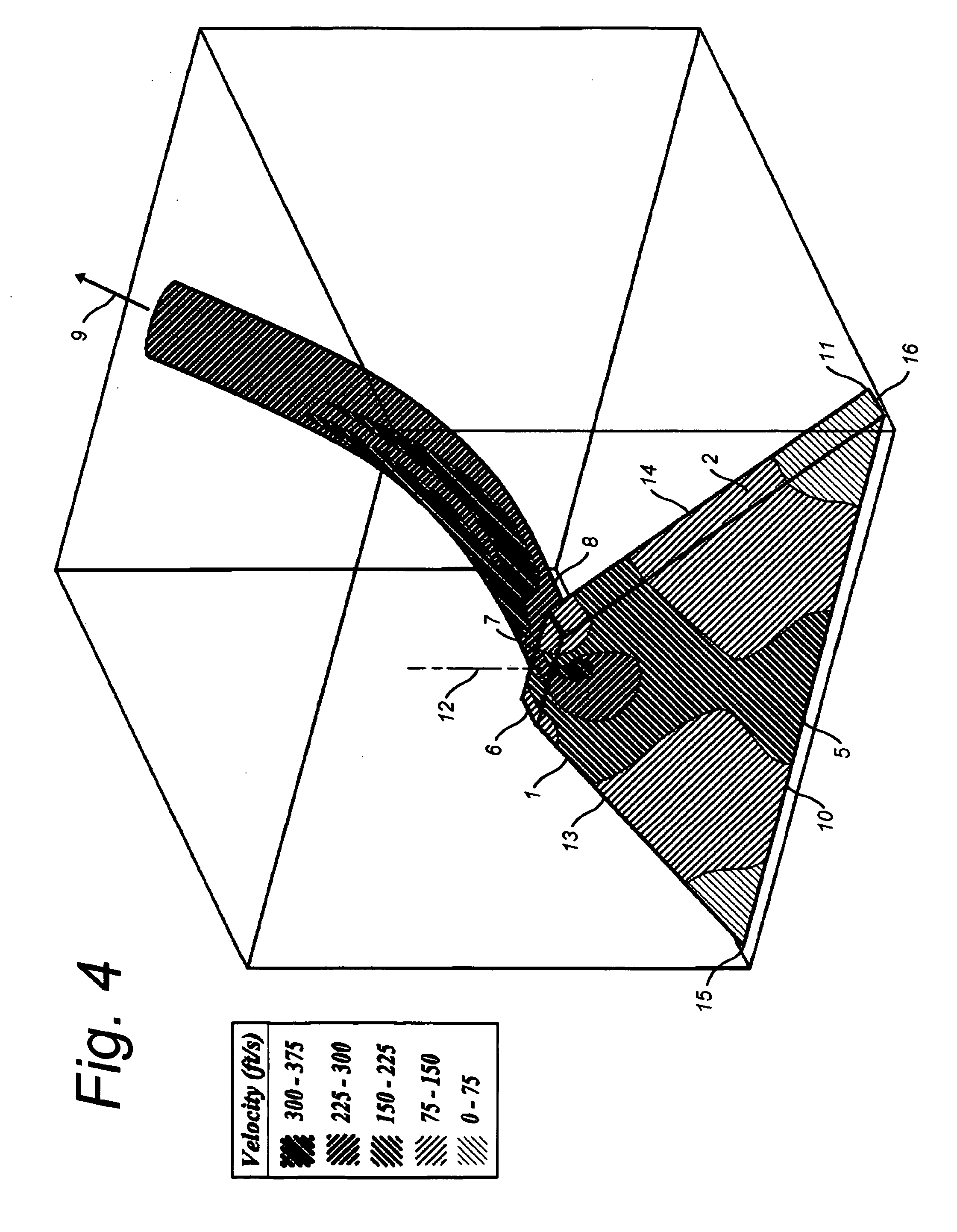
[0040]FIG. 5 is a pictorial view that illustrates one novel suction head 20 for a carpet cleaning wand, wherein a novel internal suction channel 22 (illustrated in subsequent figures) is formed within the novel suction head 20. The novel internal suction channel 22 is formed with a novel non-uniform cross section across the direction of air flow (indicated by arrow 24). The novel non-uniform cross section of the internal suction channel 22 produces dramatically more uniform flow distribution across lips 26 and 28 of an intake opening 30 that communicates with the suction channel 22. By example and without limitation, the suction head 20 is formed with a generally fan shaped body 32 having a slightly inversely arched or “swaybacked” upper body portion 34 communicating at its upper crown 36 with a with a tubular conduit 38 which is led to a suction-generator unit of a type disclosed in the prior art. The inversely arched upper...


PUM


Abstract

A novel suction head for a carpet cleaning wand wherein either or both of two designs are utilized. Each design utilizes a generally fan shaped internal suction channel that fares smoothly between an exhaust channel of substantially round cross section and lips of an intake opening having a much wider and substantially rectangular cross section. The internal suction channel utilized by one design is formed with a cross section that is non-uniform when viewed along the direction of air flow through the wand, which is a dramatic contrast to the uniform cross sections of known current designs. Another design utilizes an internal airfoil interrupting the internal suction channel along its centerline for diverting the air flow more towards the outside edges of the internal suction channel.

Description

FIELD OF THE INVENTION[0001]The present invention relates generally to wands for carpet cleaning devices, and in particular to carpet cleaning wands having uniform air flow distribution across the lips of the opening.BACKGROUND OF THE INVENTION[0002]Carpet cleaning wands are generally well-known. As illustrated in FIGS. 1, 2 and 3, such known carpet cleaning wands have a suction head 1 formed internally with an elongated hollow suction channel 2 which extends between substantially parallel spaced apart front and back surfaces 3 and 4 to an intake opening 5 that is applied to the surface to be cleaned. A hood may be provided to cover the suction head 1. The suction head 1 is coupled having the internal suction channel 2 terminating at its apex 6 in a portal 7. The portal 7 is in communication with a tubular conduit 8 directed rearwardly of the suction head 1. In operation, portal 7 is connected through the conduit 8 to a suction-generator unit which is conventional in the art of vacu...

Claims


Application Information

Patent Timeline
Patent Type & Authority Applications(United States)
IPC IPC(8): A47L9/02
CPCA47L9/02
Inventor STOY, MICHAEL A.JORDAN, NICHOLASAADLAND, NICHOLASCARROL, MICHAELDREXLER, JASONBOONE, MOSES
Owner HYDRAMASTER LLC
Why Eureka
Try Eureka