Valve mechanism for tube-type fluid container

a valve mechanism and fluid container technology, applied in the field of valve mechanisms, can solve the problems of high manufacturing cost of the valve mechanism using the spherical valve body and the spring, and achieve the effect of reliably closing the fluid

Inactive Publication Date: 2005-11-29
MASUDA MASATOSHI
View PDF19 Cites 20 Cited by
  • Summary
  • Abstract
  • Description
  • Claims
  • Application Information

AI Technical Summary

Benefits of technology

[0005]The present invention has been achieved to solve the above-mentioned problems. It aims to provide a valve mechanism which can close a fluid reliably while its configuration is simple and which can alter a flow rate of the fluid passing through the valve mechanism discretionally according to a pressure applied to the fluid.

Problems solved by technology

Manufacturing costs of the valve mechanism using the spherical valve body and the spring, however, tend to be high.

Method used


Image

  • Valve mechanism for tube-type fluid container
  • Valve mechanism for tube-type fluid container
  • Valve mechanism for tube-type fluid container

Examples


embodiment 1

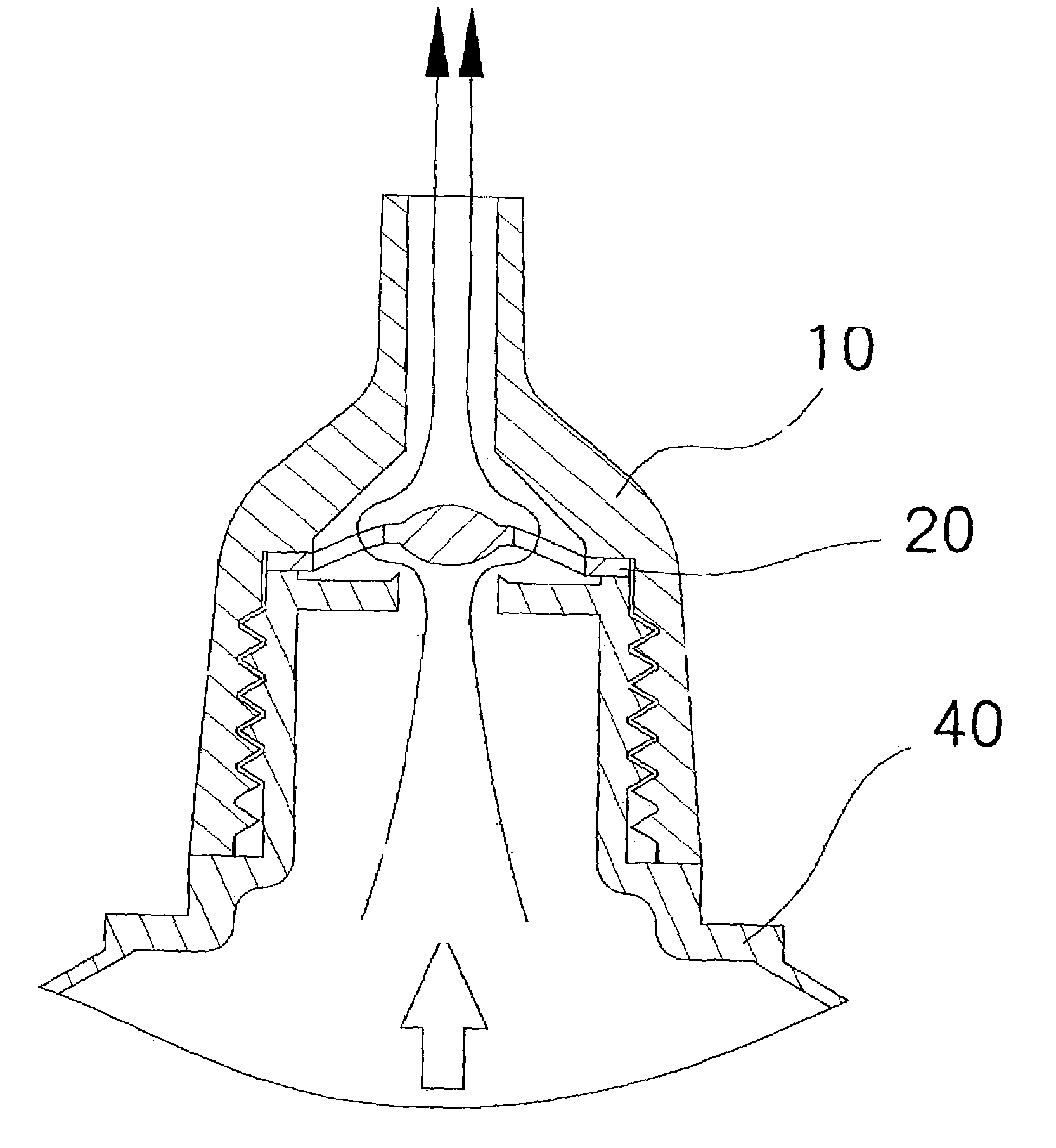
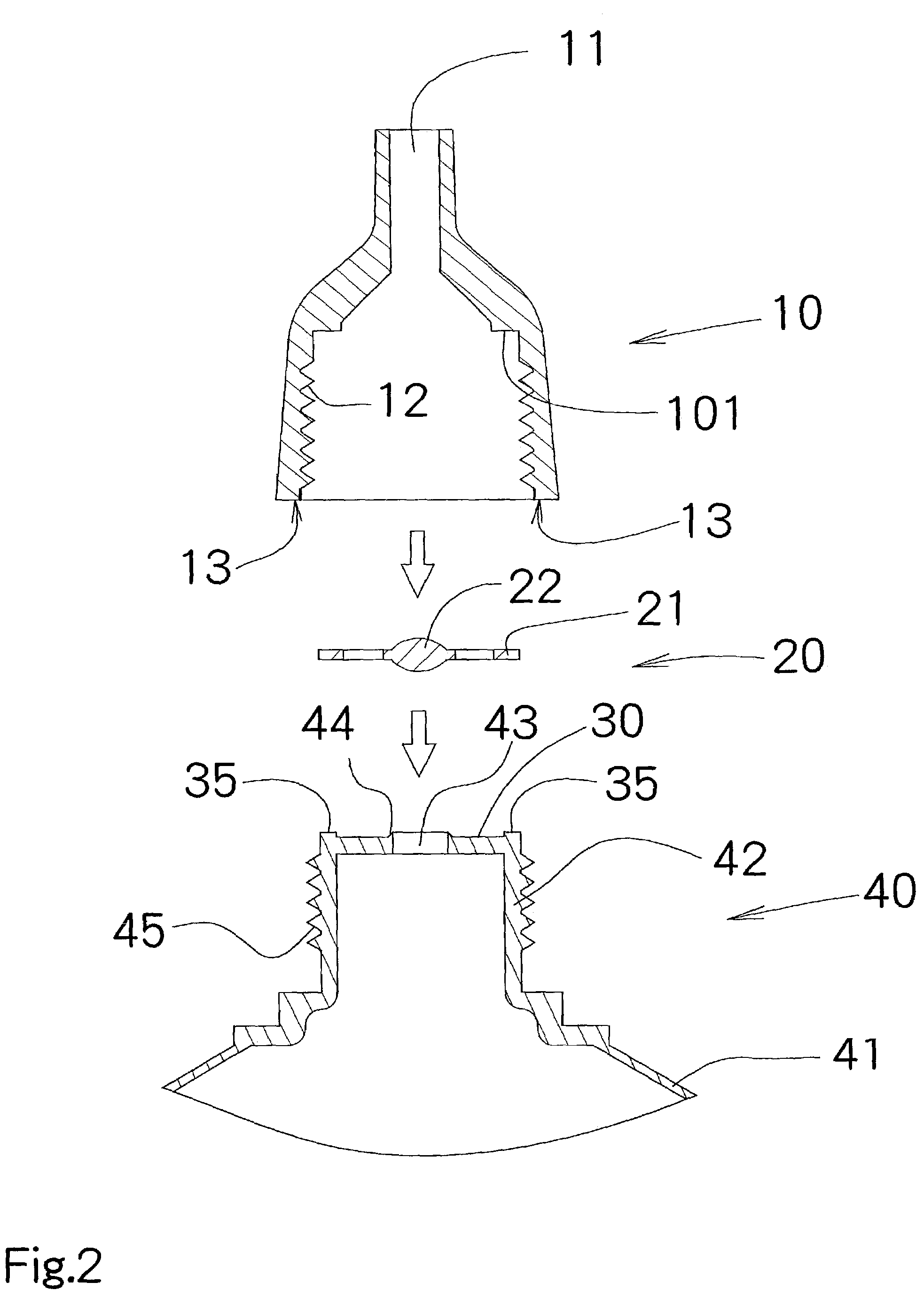
[0043]In the tube-type container to which the valve mechanism according to the above-mentioned Embodiment 1 applies, because the fixing portion 10 having a nozzle-shape, which can be used as both fixing portion and a nozzle, is adopted, the number of parts can be reduced.

[0044]An alternative embodiment of the present invention is described below. FIG. 6 is an exploded explanatory diagram showing the tube-type container to which the valve mechanism according to Embodiment 2 of the present invention applies. FIG. 7 is an exploded sectional view showing its relevant part. FIG. 8 and FIG. 9 are explanatory diagrams showing the fluid discharging motions by the tube-type container to which the valve mechanism according to Embodiment 2 of the present invention applies.

[0045]In the same manner as the tube-type container according to Embodiment 1, this tube-type container is used as a container for beauty products for storing gels such as hair gels and cleansing gels or creams such as nouris...

embodiment 2

[0055]Additionally, in the tube-type container to which the valve mechanism according to the above-mentioned Embodiment 2 applies, because the valve mechanism can be installed inside the head portion 142 in a commercially-available container main unit 40, installing an opening / closing valve feature in the opening portion of the commercially-available container main unit 40 becomes possible.

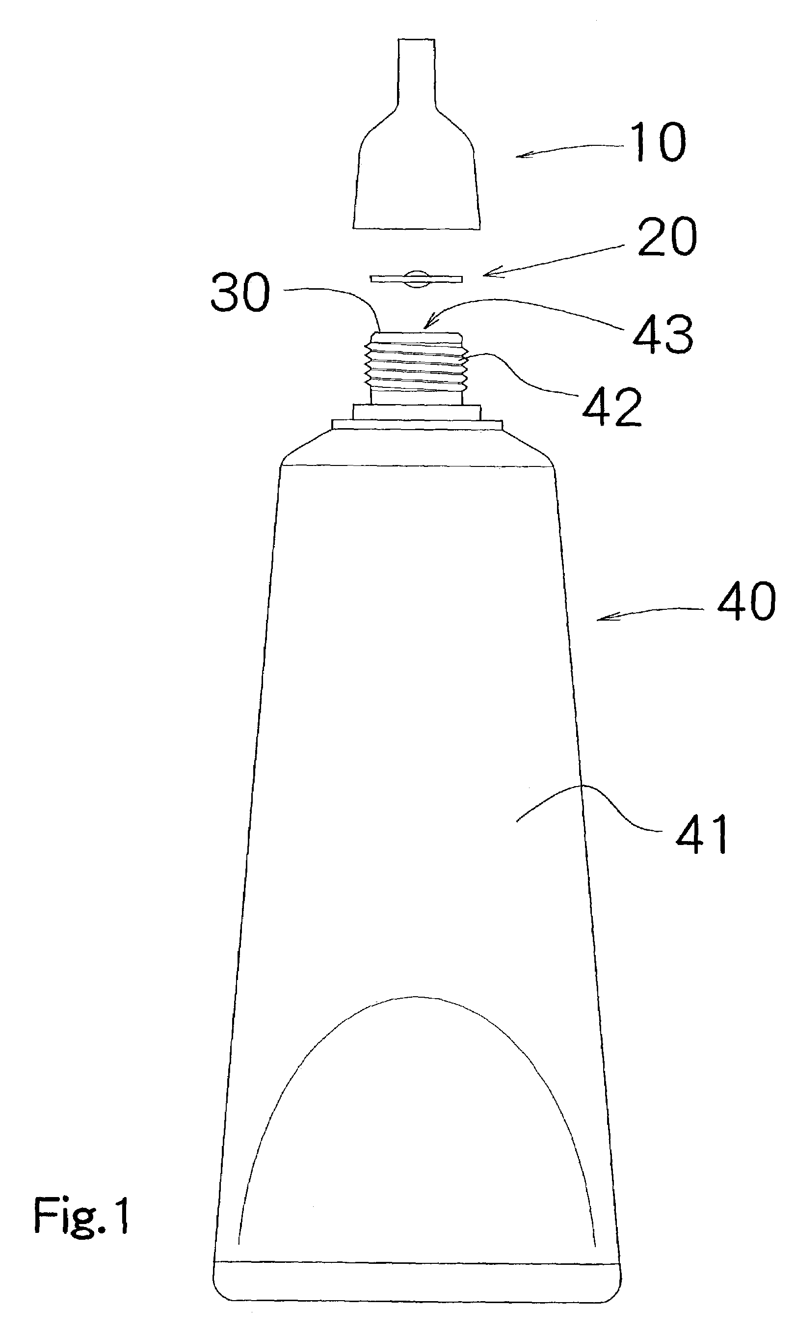
[0056]Additionally, in the above-mentioned Embodiment 2, the fixing material 110 which is nearly planate is used. A fixing material 19 having a nozzle shape similar to the one used in Embodiment 1, however, can be used as well to reduce the number of parts by using it as both a fixing material and a nozzle.

[0057]In the above-mentioned Embodiments 1 and 2, the closing portion 22 in the valve material 20 has a convex shape as well as a ring-shaped convex portion 44 facing toward the valve body 20 is formed on the outer circumferential portion of the opening portion 143 in the head portion 142 of the...


PUM


Abstract

A valve mechanism adapted for a mouth portion of a tube-type fluid container includes: a valve seat portion having an opening through which a fluid passes; a disc-shaped valve portion; and an annular fixing portion for affixing the valve portion to the valve seat portion. The valve portion includes: an annular supporting portion, a closing portion for closing the opening, and multiple connecting portions connecting the closing portion to the annular supporting portion to urge the closing portion toward the opening. The annular supporting portion, the closing portion, and the multiple connecting portions are integrally formed.

Description

BACKGROUND OF THE INVENTION[0001]The present invention relates to a valve mechanism, particularly to a valve mechanism which can be used for a tube-type fluid container.[0002]As this type of valve mechanism, for example, as described in Japanese Patent Laid-open No. 2001-179139, a valve mechanism having a spherical valve body and a spring for giving momentum to the valve body toward a valve seat has been used. Manufacturing costs of the valve mechanism using the spherical valve body and the spring, however, tend to be high.[0003]Consequently, a valve mechanism having a resinous valve seat, and a resinous valve body which moves between a closed position in which the valve body contacts the valve seat and an open position in which the valve body separates from the valve seat is commonly used.[0004]In the resinous valve mechanism, it is preferred that the valve mechanism has a simple configuration which can close a fluid flow reliably. Additionally, it is preferred that the configurati...

Claims


Application Information

Patent Timeline
Patent Type & Authority Patents(United States)
IPC IPC(8): B65D47/20B65D35/50
CPCB65D47/2075
Inventor MASUDA, MASATOSHI
Owner MASUDA MASATOSHI
Why Eureka
Try Eureka