Piezoelectric valve

a technology of piezoelectric valves and valve bodies, applied in the direction of valve details, valves, valve operating means/release devices, etc., can solve the problems of substantial load on the supporting section, relatively high production cost of flexural transducer units, etc., and achieves simple and inexpensive fashion. , the effect of few relaxation problems

Inactive Publication Date: 2008-01-29
FESTO AG & CO KG
View PDF16 Cites 20 Cited by
  • Summary
  • Abstract
  • Description
  • Claims
  • Application Information

AI Technical Summary

Benefits of technology

[0005]One object of the invention is to provide a piezoelectric valve which in a comparatively simple and inexpensive fashion renders possible a three way functionality with few relaxation problems.
[0007]It is in this manner that a piezoelectric three way valve with comparative freedom from relaxation may be produced using relatively simple means. The actuating means acting on the operational section, as for example spring means or permanent magnet means, ensure a reliable closing of the supply opening against the acting fluid pressure without subjecting the flexural transducer to danger of relaxation. Owing to the deflecting force superimposed on the actuating force, and produced by the electrical control of the flexural transducer it is possible to ensure that either the control section on the supply side or on the exit flow side closes the respectively associated controlled valve opening, while simultaneously the respectively other controlled valve opening is cleared so that the fluid to be controlled may be transferred between it and a power opening able to be connected with a load. In addition to a 3 / 2 valve functionality on the basis of the principle in accordance with the invention it is possible to relatively simply produce a 3 / 3 valve functionality as well without having to have recourse to a multiple arrangement of flexural transducers. Since hence on the basis of the basic principle a large spectrum of variations is possible, by the extensive use of identical parts, to maintain a low level of production costs.
[0010]In order to produce a 3 / 3 valve the flexural transducer is preferably so designed and arranged that in its neutral condition free of electrical voltage both control sections assume the closed position with reference to the respectively associated controlled valve opening. In connection with one design of the flexural transducer, which, given suitable electrical control, starting in the neutral position renders possible the production of a deflecting force in selectively one or the other direction, it is starting in the neutral condition possible to set a supply condition or a venting condition, either the supply opening or the exit flow opening being connected with the operational opening while simultaneously the respectively other valve opening is closed. The neutral condition corresponds in this case to a shut-off position, in which both controlled valve openings are sealingly closed by the flexural transducer.
[0018]If recourse is had to a counter abutment, which defines a counter abutment section resting linearly on the supporting section, the result is a reliable support for the flexural element so that twisting of the flexural transducer is opposed and a reliable sealing engagement of the control sections on the valve seats of the controlled valve openings is ensured.

Problems solved by technology

However, the production of the flexural transducer unit is relatively expensive.
Furthermore, there is a substantial load on the supporting section owing to the twisting forces occurring here.

Method used


Image

  • Piezoelectric valve
  • Piezoelectric valve
  • Piezoelectric valve

Examples


Embodiment Construction

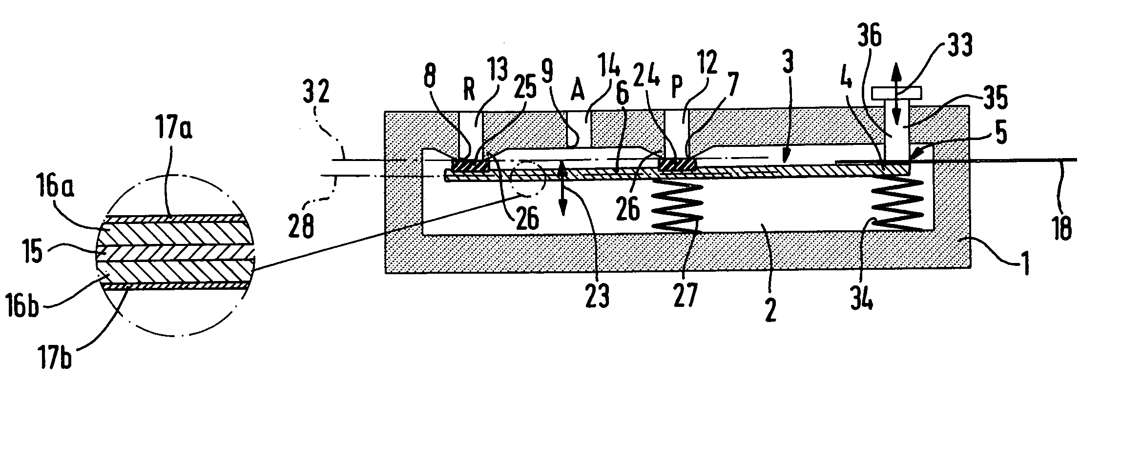
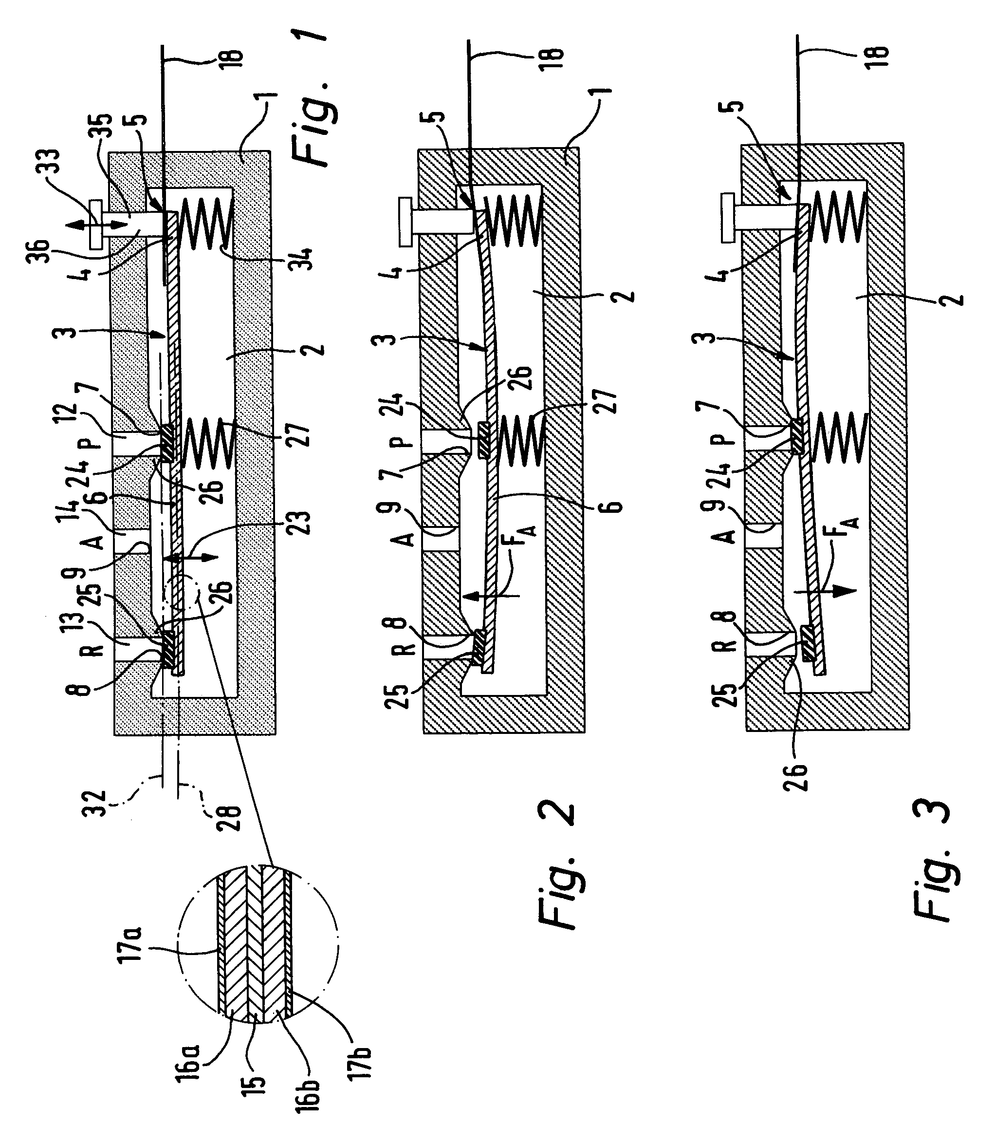
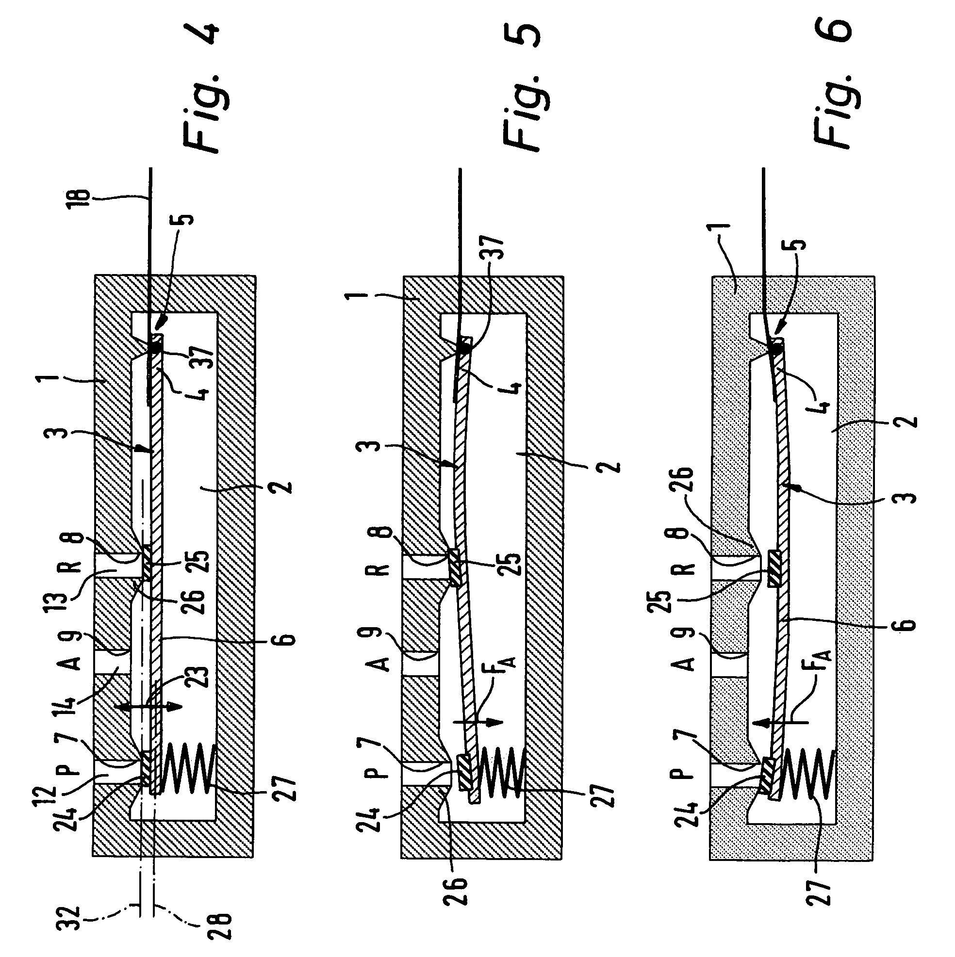
[0035]The piezoelectric valves illustrated in the drawings respectively possess a normally two-part valve housing 1 which in the interior delimits an elongated valve chamber 2. In this valve chamber 2 there is a strip-like flexural transducer 3 having an elongated form, whose rear end section forms a supporting section 4 by which it is supported directly or by way of intermediately placed support means on the valve housing 1. The position of support is referenced 5.

[0036]Starting at the support position 5 the flexural transducer 3 projects toward the opposite end. At the supporting section 4 it is adjoined by a cantilever-like operational section 6 which extends over two controlled valve openings in the form of a supply opening 7 and an exit flow opening 8.

[0037]The above mentioned controlled valve openings are the openings, facing the valve chamber 2, of two valve ducts in the form of a supply duct 12 and an exit flow duct 13. The supply duct 12 is in operation of the piezoelectric...


PUM


Abstract

A piezoelectric valve has a flexural transducer accommodated in a valve housing and having a free ending cantilever operational section able to be deflected by electrical control. The operational section extends over two controlled valve openings lying on the same side and possesses two control section associated with such valve openings. One of the control section serves for control of a supply opening and is urged into its closed by actuating means provided in addition to the flexural transducer. The actuating force is powerful enough to reach the closed position, when the other control section clears the associated valve opening.

Description

BACKGROUND OF THE INVENTION[0001]The invention relates to a piezoelectric valve comprising a flexural transducer arranged in a valve housing and having at one end a supporting section mounted by bearing means in the housing and furthermore possessing a free ending operational section, which extends in a valve chamber past two controlled valve openings in the form of a supply opening and an exit flow opening and is able to be deflected by suitable electrical control in a deflection plane athwart its longitudinal direction in order to clear each of the two controlled valve openings selectively for connection with an operational opening or by engagement with an associated valve seat to close same.THE PRIOR ART[0002]In the case of a 3 / 2 way piezoelectric valve disclosed in the European patent publication 0 538 236 B1 of this type the flexural transducer has its deflectable operational section extending between two controlled valve openings, in the case of which it is a question of a sup...

Claims


Application Information

Patent Timeline
Patent Type & Authority Patents(United States)
IPC IPC(8): F15B13/044F16K31/00
CPCF16K31/006Y10T137/86622Y10T137/86895
Inventor FRISCH, HERBERT
Owner FESTO AG & CO KG
Why Eureka
Try Eureka