Bracket for a firestop collar and use of this bracket

a technology for preventing penetration and firestop collars, which is applied in the field of firestop collars and brackets, can solve the problems of loss of intumescent materials and inability to close off penetration,

Active Publication Date: 2018-01-09
HILTI AG
View PDF33 Cites 19 Cited by
  • Summary
  • Abstract
  • Description
  • Claims
  • Application Information

AI Technical Summary

Benefits of technology

The present invention provides a bracket for a firestop collar that allows for efficient use of the collar. The bracket has an anchoring element and a pressure element that interacts with the collar. The pressure element can be moved relative to the anchoring element to expand an expansion element made of intumescent material. This allows for the collar to be actively moved in case of fire towards the penetration that is to be closed off. This systematic deformation of the collar allows its intumescent material to be directed towards the penetration, resulting in efficient use of the collar and cost savings. The bracket can be manufactured particularly cost-effectively, and can be utilized with flexible collars such as those made of fabric. The bracket ensures a more compact and reliable closure of the penetration, inhibiting the escape of fire. The bracket provides a better utilization of the expansion element and prevents the intumescent material from being squeezed out, resulting in more effective fire protection.

Problems solved by technology

This prior-art arrangement, however, entails the problem that some of the intumescent material 8 widens in the axial direction (that is to say, essentially parallel to the longitudinal axis A of the pipe 6) and is squeezed out at the opening of the penetration 4 on the wall side.
As a result, intumescent material is lost and is then not available to close off the penetration 4.

Method used


Image

  • Bracket for a firestop collar and use of this bracket
  • Bracket for a firestop collar and use of this bracket
  • Bracket for a firestop collar and use of this bracket

Examples


Embodiment Construction

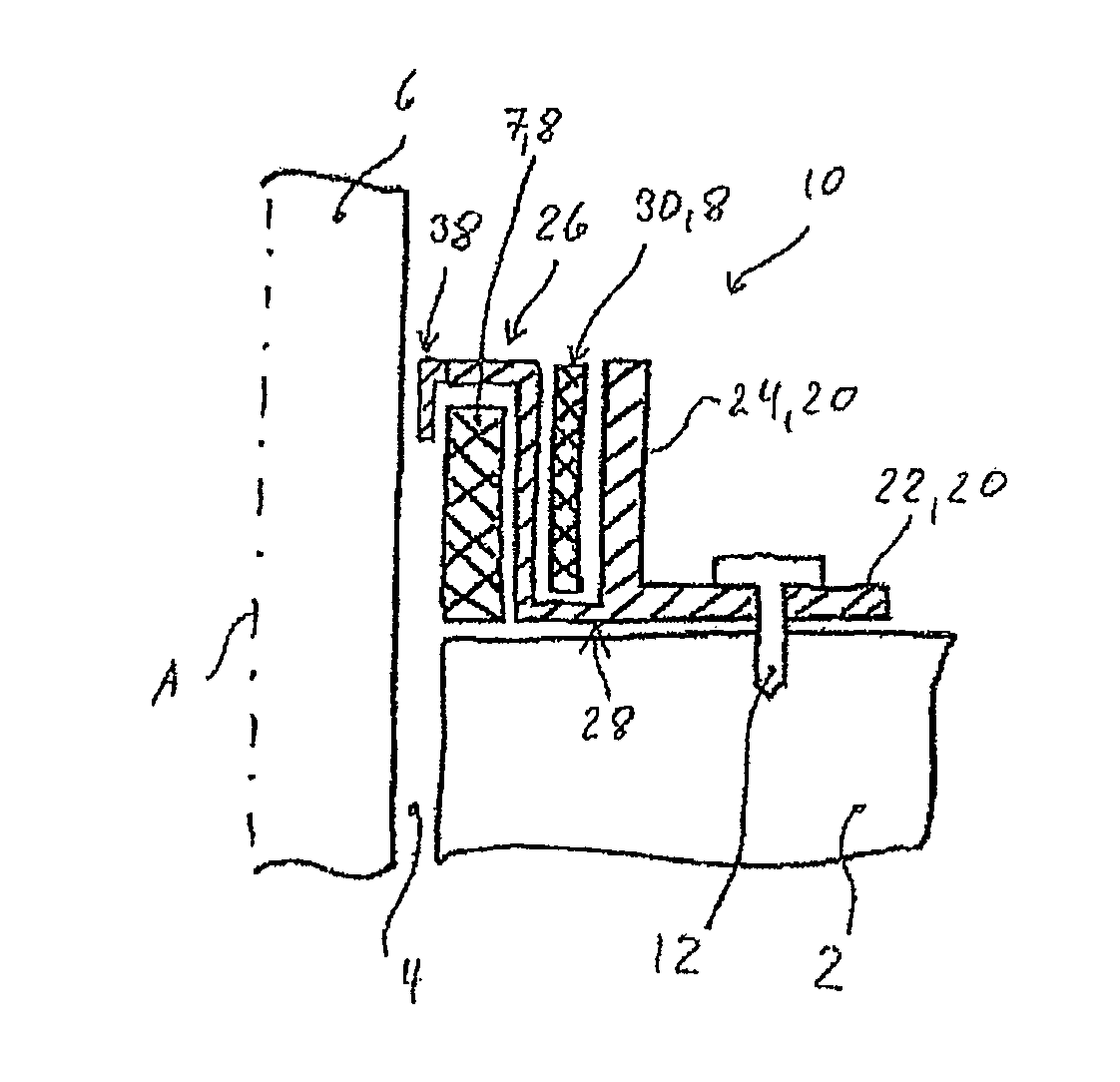
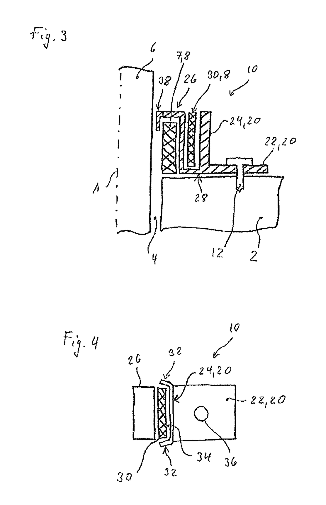
[0028]FIG. 3 shows a schematic sectional view of a bracket 10 according to a first embodiment. The bracket 10 comprises an anchoring element 20 that includes a first leg 22 and a second leg 24. The legs 22, 24 are in an L-shaped arrangement with respect to each other. The first leg 22 is fastened to a wall 2 by means of a screw 12 as the fastening element. A pressure element 26 is joined to the anchoring element 20 by means of a bending section 28 in a transition area between the first leg 22 and the second leg 24. As an alternative to the use of the bending section 28, it is also possible for the pressure element 26 and the anchoring element 20 to be pivotably joined to each other in a different manner. The use of a fabric strip or of a simple hinge is conceivable. A pivoting axis around which the pressure element 26 can be moved or pivoted relative to the anchoring element 20 is located in the transition area between the first leg 22 and the second leg 24. Preferably, the pressure...


PUM


Abstract

The anchoring element serves to anchor the bracket to a substrate, and the pressure element is intended to interact with the firestop collar. The pressure element can be moved relative to the anchoring element. An expansion element made of intumescent material is arranged between the anchoring element and the pressure element.

Description

[0001]This claims the benefit of German Patent Application DE 10 2011 084 057.5, filed Oct. 5, 2011 and hereby incorporated by reference herein.[0002]The present invention relates to a bracket for a firestop collar as well as to the use of this bracket as fastening material for a firestop collar.BACKGROUND[0003]A firestop collar arranged around pipes or cables comprises intumescent material that expands upon exposure to heat, closing off the penetration as tightly as possible so as to prevent propagation of the fire. Depending on the diameter of the penetration, the firestop collar can be arranged on an outer end of the penetration, for example, on the wall or floor / ceiling, or else directly in the penetration. When the firestop collar is arranged at the entrance to the penetration, it is normally fastened to the wall or floor / ceiling by means of brackets.[0004]This situation is shown by way of an example in FIG. 1. A wall 2 has a penetration 4 through which a pipe 6 runs that exten...

Claims


Application Information

Patent Timeline
Patent Type & Authority Patents(United States)
IPC IPC(8): E04C2/00A62C2/06F16L5/04F16L3/123H02G3/04
CPCA62C2/065F16L5/04F16L3/123H02G3/0412
Inventor PAETOW, MARIOSEMLER, RUDOLF
Owner HILTI AG
Why Eureka
Try Eureka