Liquid transfer device

Inactive Publication Date: 2009-12-31
HITACHI HIGH-TECH CORP
View PDF5 Cites 235 Cited by
  • Summary
  • Abstract
  • Description
  • Claims
  • Application Information

AI Technical Summary

Benefits of technology

[0007]The number of electrodes is reduced and control thereof is made easier, by installing the concave and convex parts on the surface of a liquid transfer device,

Problems solved by technology

However, in the case where the amount of reaction liquid is reduced, in a conventional reaction container, there was a problem of generation of air bubbles in dispensing and mi

Method used


Image

  • Liquid transfer device
  • Liquid transfer device
  • Liquid transfer device

Examples


embodiment 1

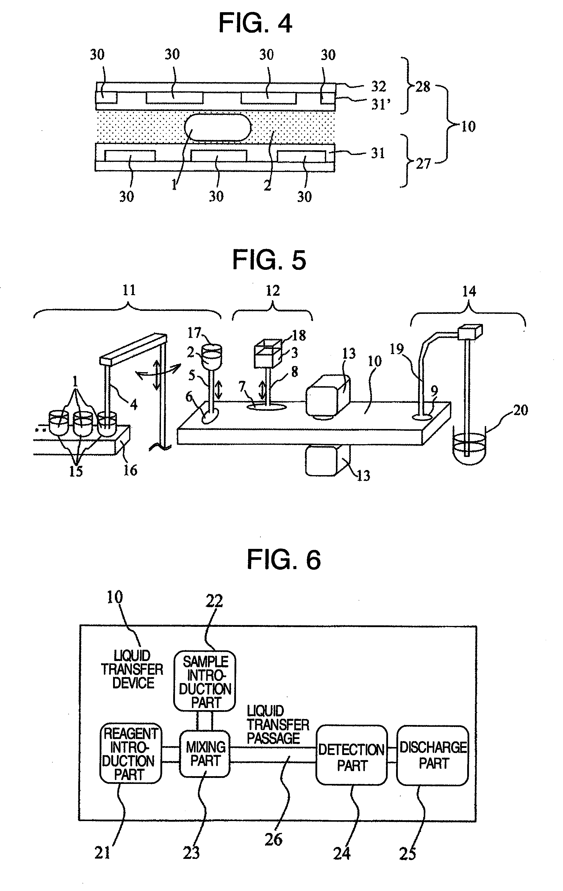
[0013]In the present embodiment, a configuration of an analysis system using a liquid transfer device is shown, where a sample and a reagent are introduced into the liquid transfer device, each thereof is transferred and then mixed to prepare reaction liquid, and after transferring the reaction liquid to a detection part, sample components are detected by absorbance measurement, and then it is discharged from the liquid transfer device.

[0014]FIG. 5 shows a total configuration of the analysis system. The analysis system is configured by the liquid transfer device 10, a sample introduction unit 11 for introducing a sample 1 and oil 2 into the liquid transfer device 10, a reagent introduction unit 12 for introducing the reagent into the liquid transfer device 10, a detection unit 13 for measuring components in the sample 1, and a discharge unit 14 for discharging the sample 1 and the oil 2 from the liquid transfer device 10. In the sample introduction unit 11, the sample 1 is, for exam...


PUM


Abstract

Provided is a liquid transfer device which controls electrically liquid position. The surface of the liquid transfer device is provided with unevenness in order to solve a problem of having a large number of electrodes for controlling voltage. The number of electrodes for controlling voltage can be halved by utilization of restoring force of liquid to a spherical shape by surface tension, in addition to electrical force.

Description

INCORPORATION BY REFERENCE[0001]The present application claims priority from Japanese application JP-2006-188786 filed on Jul. 10, 2006, the content of which is hereby incorporated by reference into this application.TECHNICAL FIELD[0002]The present invention relates to a liquid transfer device for transferring a liquid, and more specifically the present invention relates to a liquid transfer device for analysis or reaction.BACKGROUND ART[0003]As a device for analyzing quantitatively the components in a solution, an absorption spectroscopic analysis apparatus has been widely used, which irradiates a light from a light source to the solution, disperses transited transmitted light by a diffraction grating, and executes absorption measurement by each wavelength. In such an analysis apparatus, in recent years, to reduce reagent cost and lower load to environment, it has been required to reduce an amount of reaction liquid. However, in the case where the amount of reaction liquid is reduc...

Claims


Application Information

Patent Timeline
IPC IPC(8): C25B7/00
CPCB01F13/0071B01F13/0076B01L3/502792B01L2300/0819F04B19/006B01L2300/089B01L2400/0406B01L2400/0415B01L2400/0427B01L2300/0867B01F33/3031B01F33/3021
Inventor ADACHI, SAKUICHIROHARADA, KUNIOENOKI, HIDEOYAMAKAWA, HIRONOBUTSUKADA, NOBUHIRO
Owner HITACHI HIGH-TECH CORP
Why Eureka
Try Eureka