Rifle with sling and clip and method for slinging a rifle with a clip

Inactive Publication Date: 2009-12-31
SCHWEIKERT GLEN
View PDF12 Cites 8 Cited by
  • Summary
  • Abstract
  • Description
  • Claims
  • Application Information

AI Technical Summary

Benefits of technology

[0012]By reducing the burden of weight upon the shoulder and transferring this weight to the user's waistline, the

Problems solved by technology

Most backpacks are not designed for the odd shape of a gun.
The sling can a

Method used


Image

  • Rifle with sling and clip and method for slinging a rifle with a clip
  • Rifle with sling and clip and method for slinging a rifle with a clip
  • Rifle with sling and clip and method for slinging a rifle with a clip

Examples


Embodiment Construction

[0017]In the preferred embodiment, the clip is made of some sort of plastic. The plastic can be any inexpensive and durable substance like nylon of polypropylene. The clip is manufactured using plastic injection molding equipment. Such plastics have the advantage that they are cheap, reliable, sturdy, and weatherproof. Alternatively, the clip can be made of metal, such as aluminum, titanium, or some alloy.

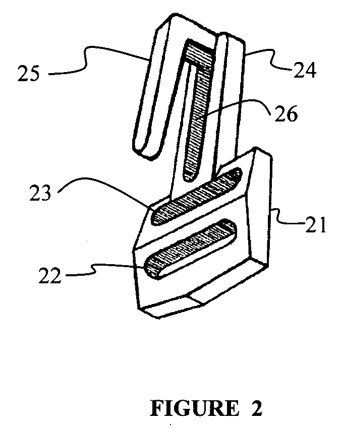
[0018]The clip in FIG. 2 is made of a solid piece of plastic. It has a slotted end 21 with slots 22 and 23. The slots can accommodate a strap or sling. The clip also has a hooked end 24 with a hook 25. A slot 26 underneath the hook 25 is also shown. The slot is not actually necessary for the function of the clip, but assists in the manufacture of the clip. With the slot 26, the clip can be made with two-piece mold. Without the extra slot, the clip can be made with a three-piece mold.

[0019]The hook on the clip is simple, straight, and snag-free. A hunter or soldier may have to use h...


PUM


Abstract

A plastic clip attaches to a gun sling, and assists in the carrying of a gun over the shoulder. The gun sling is an ordinary strap that attaches to the gun and loops over the shoulder. The clip attaches to the strap, and hooks into the waist belt. The clip allows the waist belt to support much of the weight of the gun, and keeps the gun from flopping around. The gun is further stabilized by a bungee cord that connects the clip to a belt loop.

Description

CROSS-REFERENCE TO RELATED APPLICATIONS[0001]This application is a continuation of U.S. patent application Ser. No. 10 / 957,997 to Schweikert, filed Oct. 4, 2004.BACKGROUND[0002]1. Field of the Invention[0003]This invention relates to straps and fasteners.[0004]2. Description of Related Art[0005]Hunters, soldiers, and others who have to carry a rifle often use shoulder sling. The sling is a strap that holds a gun, usually a rifle or shotgun, and extends over the shoulder. The weight of the gun is supported by the shoulder, and the sling leaves the hands free.[0006]Backpacks also commonly use shoulder straps to support a load. Because backpacks can be quite heavy, some backpacks have belts that go around the waist. A belt can support much of the weight of a backpack on the hips, as the hips can hold more weight that the shoulders.[0007]A soldier might carry a gun and backpack, but he will usually not put the gun in the backpack. Most backpacks are not designed for the odd shape of a g...

Claims


Application Information

Patent Timeline
IPC IPC(8): F41C33/00
CPCF41C33/002Y10S224/913
Inventor SCHWEIKERT, GLEN
Owner SCHWEIKERT GLEN
Why Eureka
Try Eureka