Fixing device and image forming device

a technology of fixing device and image forming device, which is applied in the direction of instruments, electrographic process devices, optics, etc., can solve the problem of unfavorable fixing of toner

Active Publication Date: 2009-12-31
OKI DATA CORP
View PDF2 Cites 13 Cited by
  • Summary
  • Abstract
  • Description
  • Claims
  • Application Information

AI Technical Summary

Benefits of technology

[0009]The present invention reduces the difference in temperature between a medium-contacting part and a non-medium-contacting part o

Problems solved by technology

When an image is fixed to a wide-width medium (WWM) just after that, the fixing temperature differs between the m

Method used


Image

  • Fixing device and image forming device
  • Fixing device and image forming device
  • Fixing device and image forming device

Examples


first embodiment

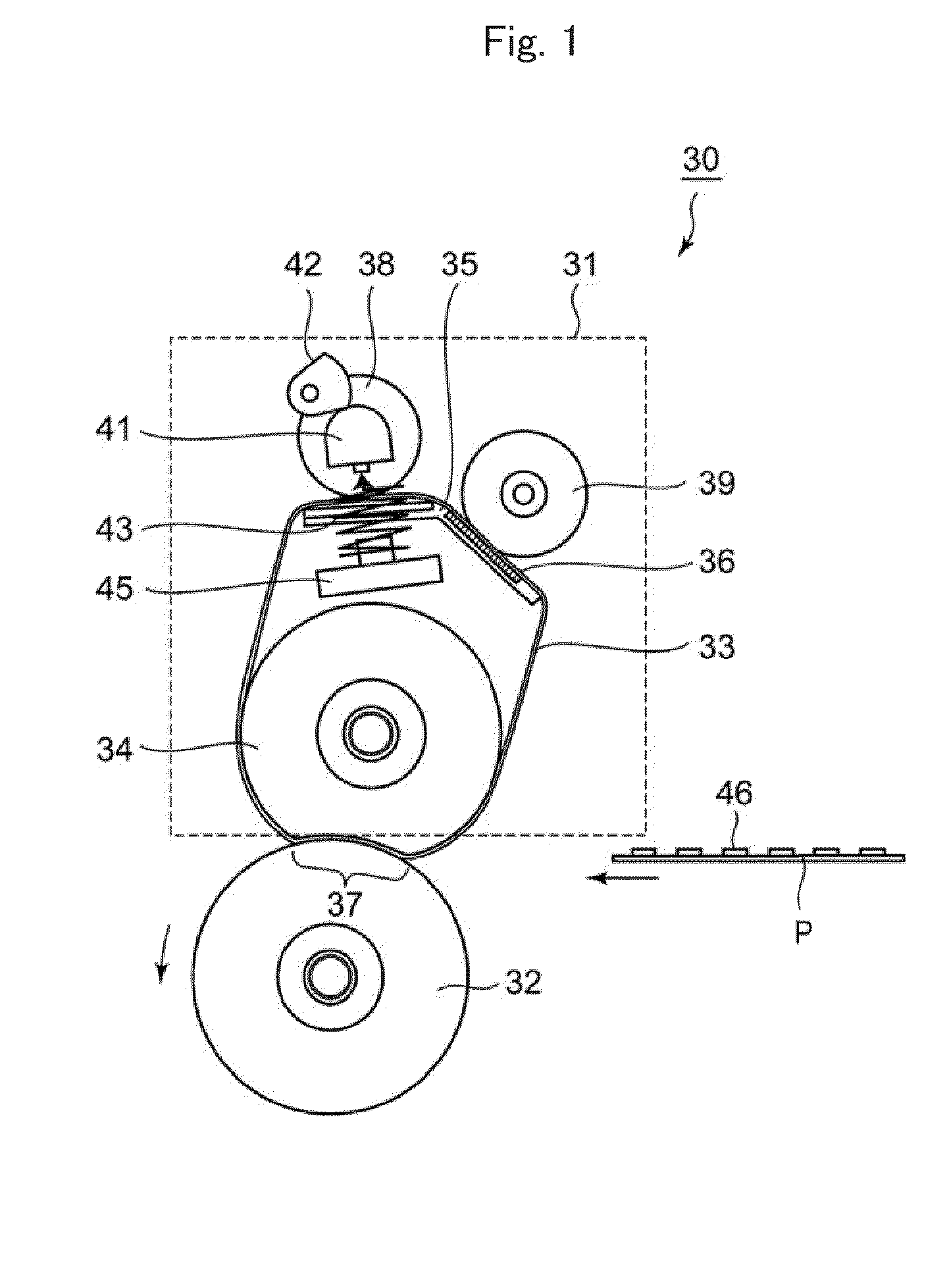
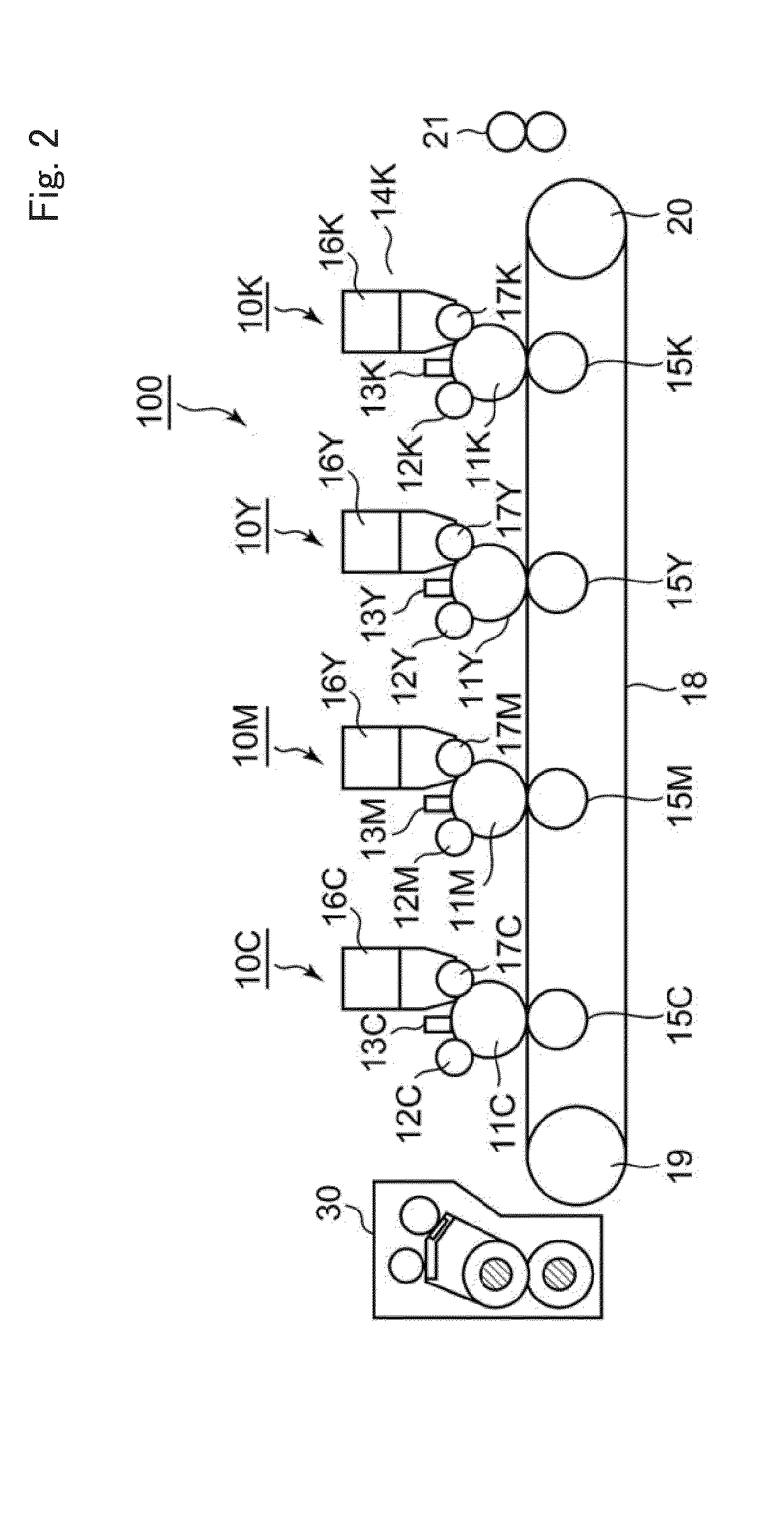
[0024]Identical reference characters are used to designate common elements among different embodiments. In addition, in each embodiment described below, an electrophotographic printer is described as an example of an image forming device. FIG. 1 illustrates a side view of a fixing device 30 of a first embodiment. FIG. 2 illustrates a schematic configuration view of an electrophotographic printer 100 including the fixing device 30 of the first embodiment. Initially, the electrophotographic printer 100 is described according to FIG. 2.

[0025]In FIG. 2, the electrophotographic printer 100 includes image forming units 10K, 10Y, 10M, and 10C of black, yellow, magenta, and cyan, respectively. Only the image forming unit 10K of black is described, since the configuration of each image forming unit 10K, 10Y, 10M, and 10C is similar. In the image forming unit 10K, a photoconductive drum 11K as an image supporter, an electrostatic roller 12K, which evenly charges the surface of the photoconduc...

second embodiment

[0053]Next, the second embodiment is described. FIG. 11 illustrates a side view of a fixing device 60 of the second embodiment, and FIG. 12 illustrates a perspective view of the fixing device 60 of the second embodiment. The fixing device 60 of the second embodiment is configured to press an NWM contacting part D of a fixing belt 33 against a heat transfer member 35 and to simultaneously disengage the fixing belt 33 from a heat source 36, when an image is fixed on a narrow-width medium P.

[0054]In FIGS. 11 and 12, a pressure roller 32, a fixing belt 33, a fixing roller 34, a heat transfer member 35, a heat source 36, a central pressing roller 38, a cam 42, and a compression spring 43 are arranged in the fixing device 60, in a manner similar to the fixing device 30 of the first embodiment. The shape of the heat transfer member 35 is the same as that of the first embodiment.

[0055]An end part 61a of a dogleg shaped arm member 61 is attached to an end part of a shaft 40 of the central pr...


PUM


Abstract

A fixing device comprise an endless fixing belt; a first heater that heats a first predetermined section of the fixing belt, a second heater that heats a second predetermined section of the fixing belt, a switch that determines whether or not the second predetermined section of the fixing belt is heated by the second heater, a controller controls a switching operation of the switch according to a size of a medium on which an image is fixed by the fixing belt, and a temperature controller that reduces a heating temperature of the first heater when the second predetermined section of the fixing belt is heated by the second heater.

Description

[0001]The present application is related to, claims priority from and incorporates by reference Japanese Patent Application No. 2008-169834, filed on Jun. 30, 2008.TECHNICAL FIELD[0002]The present invention relates to a fixing device that fixes a toner image to a medium in an image forming device that uses an electrophotographic, for example, a printer, a copying machine, and a facsimile machine.BACKGROUND[0003]A fixing device for fixing a toner image is used in an electrophotographic image forming device, for example, a printer, a copying machine, and a facsimile machine, as a fixing device. A known fixing device using an endless belt (a fixing belt) is effective in power-saving or improving a rise time speed in contrast with the conventional heat roller method. For example, Japanese laid-open patent application No. 2007-322888 discloses a fixing device using such a fixing belt.[0004]In a fixing device using a fixing belt, a fixing roller is arranged in a position that is counter t...

Claims


Application Information

Patent Timeline
IPC IPC(8): G03G15/20
CPCG03G15/2042
Inventor KOBAYASHI, KEI
Owner OKI DATA CORP
Why Eureka
Try Eureka