Multiple phase center feedhorn for reflector antenna

a reflector antenna and multi-phase technology, applied in waveguide horns, antennas, electrical equipment, etc., can solve the problems of mechanical fixation of phase center separation, difficult to distinguish difficulty in detecting a target from stationary background clutter, etc., to reduce the overall system noise temperature, reduce the loss of gain, and be easily adaptable

Inactive Publication Date: 2007-02-20
HER MAJESTY THE QUEEN AS REPRESENTED BY THE MINIST OF NAT DEFENCE OF HER MAJESTYS CANADIAN GOVERNMENT
View PDF12 Cites 238 Cited by
  • Summary
  • Abstract
  • Description
  • Claims
  • Application Information

AI Technical Summary

Benefits of technology

[0011]The invention is advantageous in that there is a minimal loss of gain in the beam pattern over that for a comparative single phase center antenna. Another advantage is that the phase center separation and constant phase beamwidths may be adjusted by adjusting the drive parameters. A further advantages arises from the fact that the multiple phase centers are extracted from a single physical aperture which is intrinsically matched, thus reducing the overall system noise temperature. Yet another advantage is that the invention may be easily adapted to provide an antenna responsive to different polarizations.
[0012]Advantageously the invention allows an antenna to be operated with a single phase center for a transmission and multiple phase centers for a reception without any substantial increase in complexity.

Problems solved by technology

In MTI systems it may become difficult to discern a target from stationary background clutter when the target is moving slowly with respect to the terrain.
This approach has several disadvantages, one being that the antenna directivity is limited to that of each individual antenna and not that implied by the physical span of the collective multiple antennae.
Another disadvantage is that the phase center separation is mechanically fixed which also fixes the constant phase beamwidths.
Finally, the system noise temperature increases linearly with the number of mismatched antenna apertures.
Where more than two phase centers are required the problem is further exaggerated.
Another disadvantage is that close placement of the feedhorns 102 and 104 commonly results in mutual coupling which may affect receiver discrimination.
Furthermore, since MTI relies to a great extent on channel homogeneity the, the driving network for the feedhorns becomes increasingly complex requiring the provision of facilities for the calibration of the multiple beams.
Yet another disadvantage is that, again, the phase center separation can only be changed by mechanical means.
Furthermore for radar antenna that require rotation at high angular velocity, the added mass and pointing stability may also become an issue.

Method used


Image

  • Multiple phase center feedhorn for reflector antenna
  • Multiple phase center feedhorn for reflector antenna
  • Multiple phase center feedhorn for reflector antenna

Examples


Embodiment Construction

[0026]For an understanding of the invention, reference will now be made by way of example to a following detailed description in conjunction with the accompanying drawings in which like numerals refer to like structures.

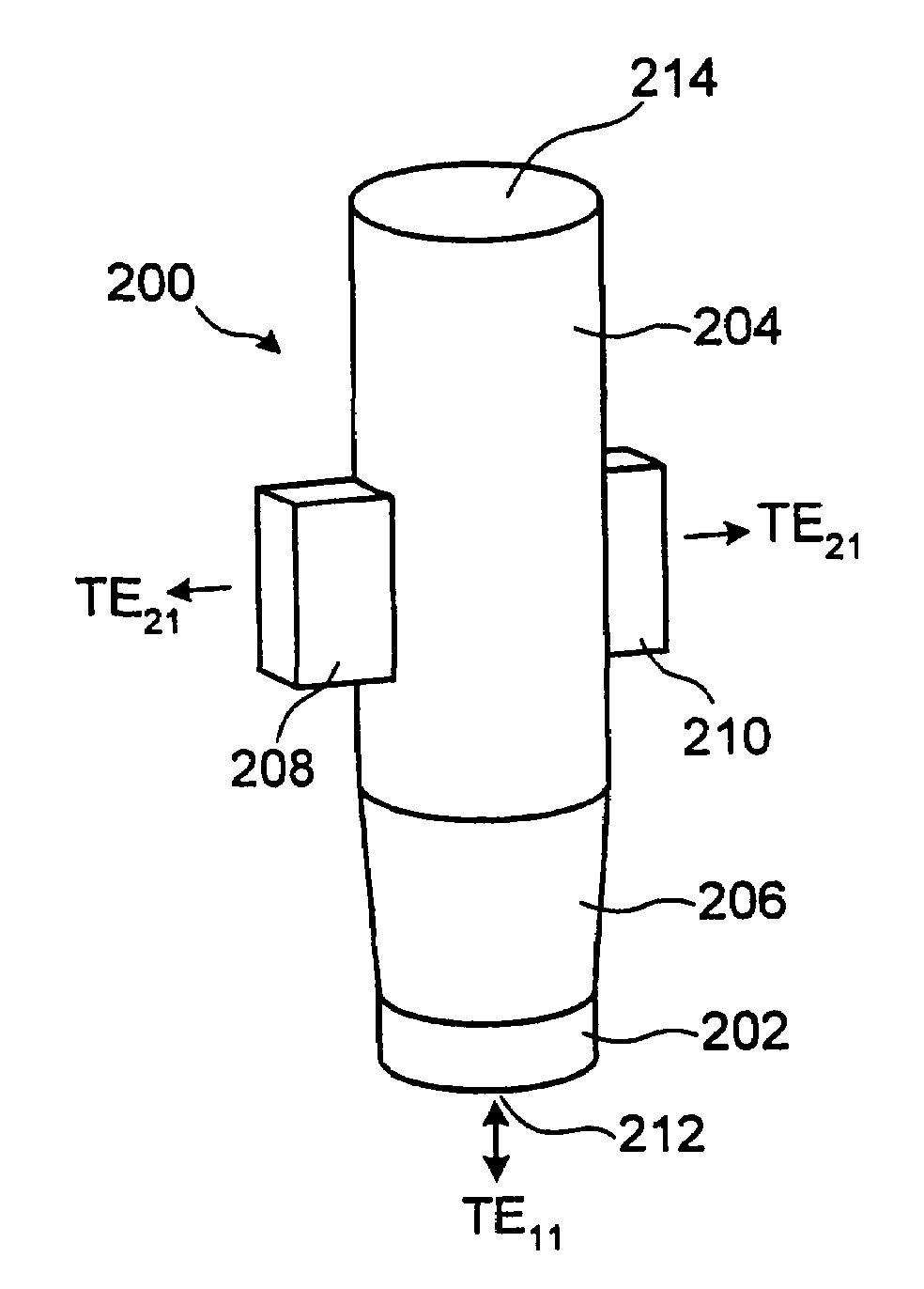
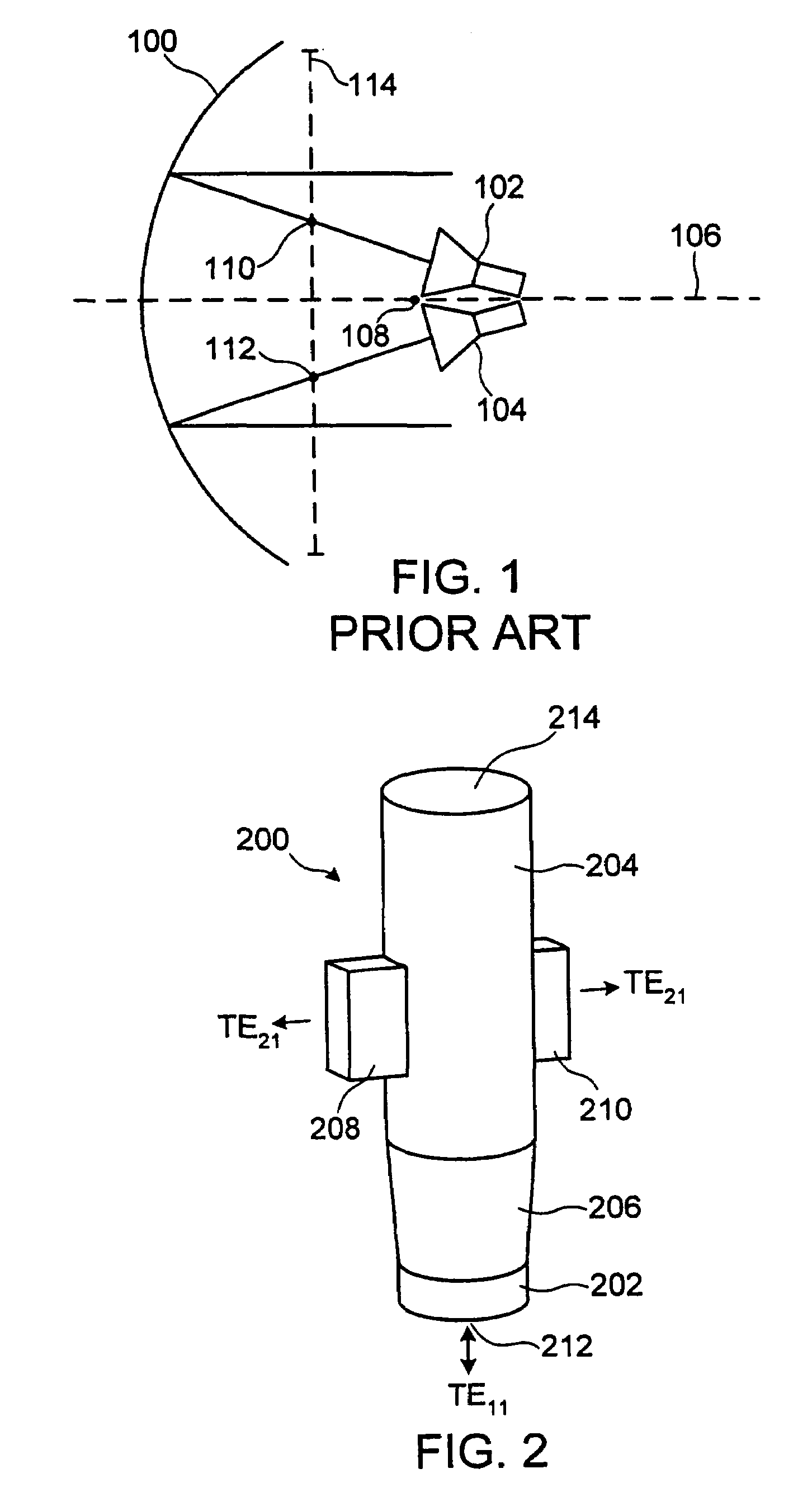
[0027]In accordance with a first embodiment of the invention, FIG. 2 shows a multimode feedhorn 200 comprising a lower circular waveguide 202 and a circular waveguide horn section 204 joined by a tapered waveguide section 206. A pair of rectangular waveguides 208 and 210 are transversely connected to opposite sides of the feedhorn 204. The diameter of waveguide 202 is selected such that, at the design frequency, only the dominant TE11 mode is able to propagate. The diameter of the horn section 204 is chosen such that a TE21 secondary mode is able to co-exist with the TE11 mode.

[0028]The TE11 mode is extracted via port 212 and the TE21 mode is symmetrically extracted via transversely located waveguides 208 and 210. Feedhorn 200 also includes an opening 214. The desire...


PUM


Abstract

A feedhorn driving method and apparatus allows the establishment of multiple phase centers using only a single multimode feedhorn. At least two higher-order modes are extracted from the feedhorn and weighted in amplitude and phase. The phase center separation is established in accordance with an assigned weights. The feedhorn has application in i.a. moving target indication systems.

Description

[0001]This application claims benefit of the filing date of U.S. Provisional Application No. 60 / 480,742 filed on Jun. 24, 2003.BACKGROUND OF THE INVENTION[0002]The invention relates generally to radio wave antennae, and more particularly to multiple phase center radio wave antennae.[0003]Multiple phase center antennae are used in some specialized communications and radar applications. Specific radar applications may include ground or airborne moving target indication (MTI), along with track interferometry and maritime surveillance. In MTI systems it may become difficult to discern a target from stationary background clutter when the target is moving slowly with respect to the terrain. Clutter is the term used in radar applications, to describe confusing or unwanted reflections that interfere with the observation of desired signals on a radar indicator. Clutter may be suppressed by receiving reflected radiation beams via multiple radar channels and employing adaptive filtering to ide...

Claims


Application Information

Patent Timeline
Patent Type & Authority Patents(United States)
IPC IPC(8): H01Q13/00H01Q13/02H01Q19/12H01Q25/00
CPCH01Q13/025H01Q25/00H01Q19/12
Inventor BALAJI, BHASHYAMDAMINI, ANTHONYHASLAM, GEORGE E.SHAFAI, LOTFOLLAHSHARMA, SATISH
Owner HER MAJESTY THE QUEEN AS REPRESENTED BY THE MINIST OF NAT DEFENCE OF HER MAJESTYS CANADIAN GOVERNMENT
Why Eureka
Try Eureka