
Output stage circut for an operational amplifier

a technology of output stage and amplifier, which is applied in the field of amplifiers, can solve the problems of low gain complications, and difficult to achieve better amplifiers and output stages. , to achieve the effect of enhancing the gain of the output stage circuit, and reducing the loss of gain

Inactive Publication Date: 2005-10-13
ZHANG JOY Y +1
View PDF4 Cites 4 Cited by
  • Summary
  • Abstract
  • Description
  • Claims
  • Application Information

AI Technical Summary

Benefits of technology

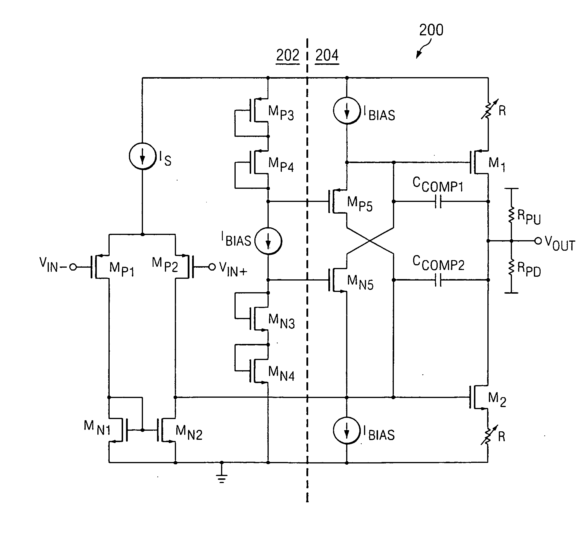
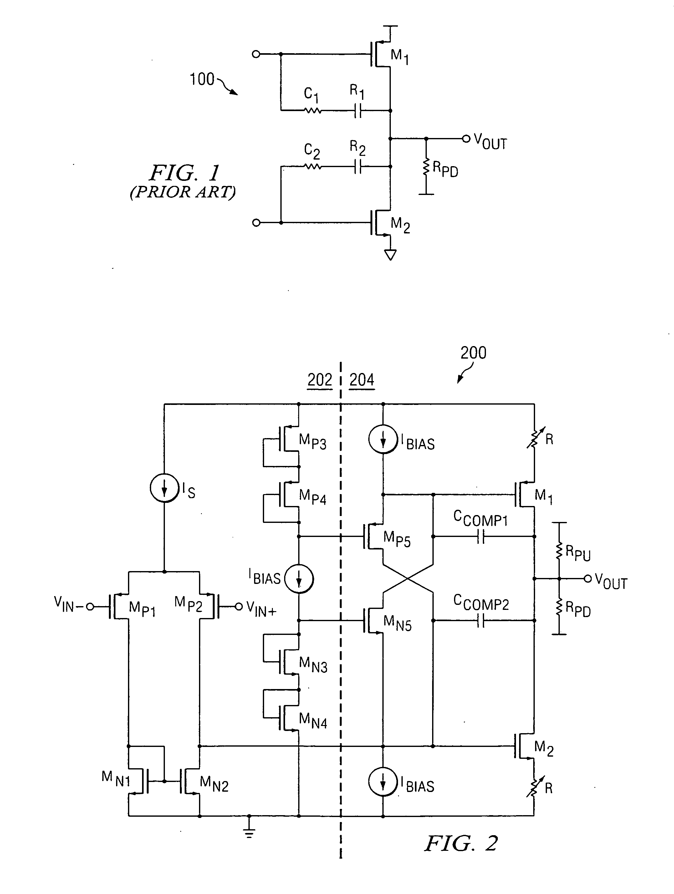
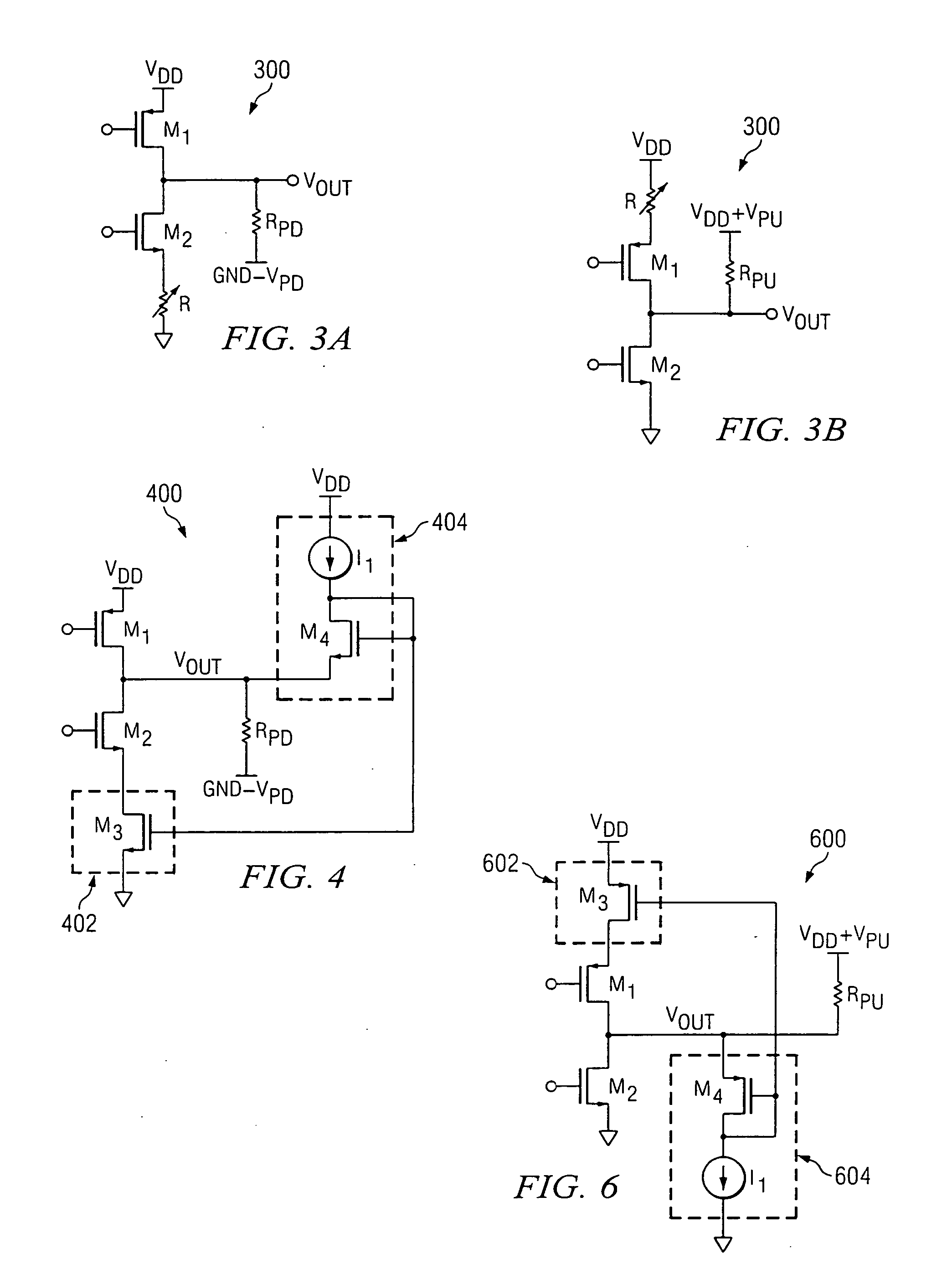
"The present invention provides an output stage circuit that allows an operational amplifier circuit to output a signal with minimal loss of gain. This circuit includes a pair of output transistors and a controlled resistive circuit that enhances the gain of the output stage circuit during the pulling up or down of the output voltage towards an upper or lower power supply. The controlled resistive circuit modifies the dynamic impedance effect of the output transistor during pull-up or pull-down operation. The output stage circuit can be used in various operational amplifier configurations and can allow for low voltage processes to be utilized."

Problems solved by technology

For most single supply operational amplifiers, difficulties arise when the output signal is pulled downwards to the lower output swing limit, such as to ground or below.
Unfortunately, even the better amplifiers and output stages are only able to swing close to single supply ground, for example within approximately 10 mV, well short of the approximate 1 μV or less that is desired.
Further, when output voltage at VOUT is close to zero volts or ground, output transistor M2 will tend to operate within the deep triode region, acting effectively as a resistor, thus resulting in low gain complications, and thus slower speeds.
However, pull-down resistor RPD does not address the lower gain characteristics caused by output transistor M2 during pulling-down of output voltage VOUT, output stage 100 still realizes reduced speed.
However, such dual supply operational amplifiers generally require higher voltage processes than the low voltage processes utilized by single supply operational amplifiers.

Method used


Image

  • Output stage circut for an operational amplifier
  • Output stage circut for an operational amplifier
  • Output stage circut for an operational amplifier

Examples


Embodiment Construction

[0018] The present invention may be described herein in terms of various functional components. It should be appreciated that such functional components may be realized by any number of hardware or structural devices configured to perform the specified functions. For example, the present invention may employ various integrated components, e.g., buffers, supply references, current sources, signal conditioning devices and the like, comprised of various electrical devices, e.g., resistors, transistors, capacitors, diodes and other components whose values may be suitably configured for various intended purposes. In addition, the present invention may be practiced in any integrated circuit application where an output stage can be utilized. However for purposes of illustration only, exemplary embodiments of the present invention are illustrated herein in connection with an operational amplifier, for example one having a class AB output configuration. Further, it should be noted that while...


PUM


Abstract

An output stage circuit is configured for enabling an output of an amplifier circuit to be pulled upwards and / or downwards to or beyond an upper power supply or below a lower power supply. The exemplary output stage circuit comprises a pair of output transistors configured to provide an output voltage, and a controlled resistive circuit. The controlled resistive element is configured to enhance the gain of the output stage circuit by modifying the dynamic impedance effect of the upper output transistor during pull-up operation, or the lower output transistor during pull-down operation. During normal operation, the controlled resistive element operates with low resistance, e.g., acts as a “short,” but during the pull-up or pull-down operation the controlled resistive element can be configured to add resistance to modify the dynamic impedance of the upper or lower output transistor. As a result, an amplifier circuit including an exemplary output stage circuit can swing towards or beyond an upper and / or lower power supply with minimal gain loss for the amplifier circuit, thus allowing for low voltage processes to be utilized.

Description

TECHNICAL FIELD [0001] The present invention relates, generally, to amplifiers. More particularly, the present invention relates to an output stage circuit for an operational amplifier that can facilitate the pulling-up and / or pulling-down of the output of the operational amplifier towards or beyond an upper and / or lower power supply. BACKGROUND OF THE INVENTION [0002] In the efforts for optimizing and improving operation in various high-speed microcontroller-based devices, such as various instrumentation and measurement equipment and the like, significant attention has been given to the further improvement of the high-speed operational amplifiers utilized. For example, efforts have been made to improve transimpedance amplifiers that are used to convert low-level photodiode currents to usable voltage signals, and are commonly implemented within low-current and leakage current measurement applications, as well as other low-level sensor current applications. [0003] Many operational am...

Claims


Application Information

Patent Timeline
Patent Type & Authority Applications(United States)
IPC IPC(8): H03F3/18H03F3/30H03F3/45
CPCH03F3/3022H03F3/45183H03F2203/45288H03F2203/45632H03F2203/45644H03F2203/45686
Inventor ZHANG, JOY Y.BURT, RODNEY T.
Owner ZHANG JOY Y
Learn More