Battery Module Having Cooling Manifold and Method for Cooling Battery Module

a battery module and cooling manifold technology, which is applied in the manufacture of cell components, final products, electrochemical generators, etc., can solve the problem that the cooling system may not uniformly cool battery cells in the battery pack

Active Publication Date: 2009-12-31
LG ENERGY SOLUTION LTD
View PDF99 Cites 72 Cited by
  • Summary
  • Abstract
  • Description
  • Claims
  • Application Information

AI Technical Summary

Problems solved by technology

However, an existing cooling system may not uniformly cool battery cells in a battery pack.

Method used


Image

  • Battery Module Having Cooling Manifold and Method for Cooling Battery Module
  • Battery Module Having Cooling Manifold and Method for Cooling Battery Module
  • Battery Module Having Cooling Manifold and Method for Cooling Battery Module

Examples


Embodiment Construction

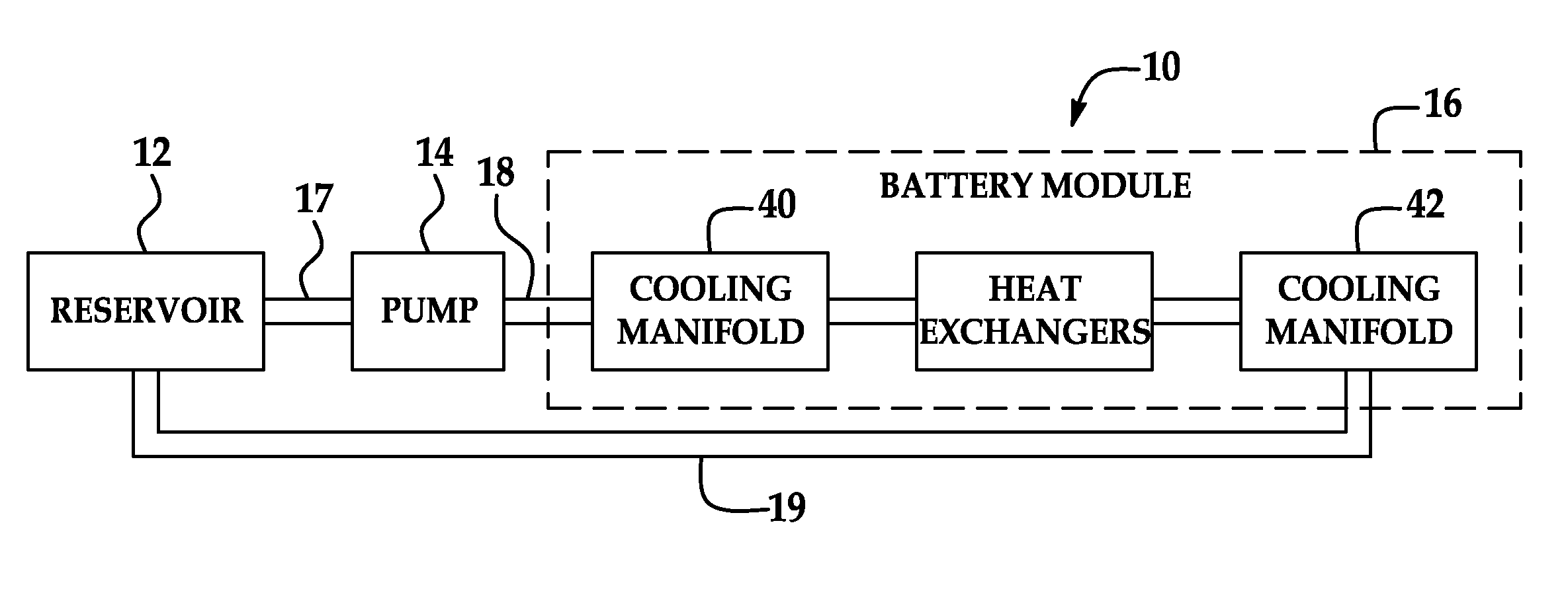
[0014]Referring to FIG. 1, a system 10 for cooling a battery module 16 is illustrated. The system 10 includes a reservoir 12, a pump 14, and conduits 17, 18 and 19. The reservoir 12 holds a fluid therein. The pump 14 pumps the fluid from the reservoir 12 via the conduit 17. Thereafter, the pump 14 pumps the fluid into the battery module 16 via the conduit 18. The battery module 16 includes a cooling manifold 40, heat exchangers, and a cooling manifold 42 that will be explained in greater detail below. The cooling manifold 40 is configured to provide a substantially equal flow rate of the fluid through each of the respective heat exchangers in the battery module 16 such that the battery cells therein have a substantially equal amount of heat energy removed from the battery cells. Thus, all of the battery cells in the battery module 16 are maintained at a substantially similar temperature resulting in the battery cells having uniform operational characteristics including output voltag...


PUM

PropertyMeasurementUnit
flow rateaaaaaaaaaa
output voltagesaaaaaaaaaa
heat energyaaaaaaaaaa

Abstract

A battery module having a cooling manifold is provided. The battery module includes a plurality of battery cell assemblies having a plurality of heat exchangers. The battery module further includes the cooling manifold operably coupled to the plurality of battery cell assemblies. The cooling manifold has a manifold portion and a cover plate. The manifold portion has a peripheral wall, a rear wall coupled to the peripheral wall, and a flow diverter. The peripheral wall has a top portion with an inlet aperture extending therethrough. The rear wall has a plurality of outlet apertures extending therethrough. The cover plate is coupled to the peripheral wall opposite to the rear wall. The flow diverter extends from the rear wall and is disposed below the inlet aperture. The flow diverter is configured to receive fluid from the inlet aperture and to divert the fluid so that a substantially equal flow rate of the fluid is obtained through each outlet aperture of the plurality of outlet apertures to a respective heat exchanger of the plurality of heat exchanger for cooling the plurality of battery cell assemblies.

Description

TECHNICAL FIELD[0001]This application relates generally to a battery module having a cooling manifold and a method for cooling the battery module.BACKGROUND OF THE INVENTION[0002]Battery packs generate heat during usage. To prevent degradation of the battery packs, the battery packs should be cooled. However, an existing cooling system may not uniformly cool battery cells in a battery pack. The inventors herein have recognized that if battery cells in a battery pack are not uniformly cooled, the battery cells can undesirably have differing operational characteristics including differing output voltages.[0003]Accordingly, the inventors herein have recognized a need for a battery module having a cooling manifold that eliminates and / or reduces the above mentioned deficiencySUMMARY OF THE INVENTION[0004]A battery module in accordance with an exemplary embodiment is provided. The battery module includes a plurality of battery cell assemblies having a plurality of heat exchangers. The bat...

Claims


Application Information

Patent Timeline
Patent Type & Authority Applications(United States)
IPC IPC(8): H01M10/50H01M50/77
CPCH01M10/5004H01M10/5008H01M10/5032H01M10/5077H01M10/5059H01M10/5073H01M10/5036H01M10/647H01M10/6568H01M10/6557H01M10/617H01M10/6566H01M10/651H01M10/613Y02E60/10Y02P70/50H01M50/20
Inventor KOETTING, WILLIAMPAYNE, JOSH
Owner LG ENERGY SOLUTION LTD
Why Eureka
Try Eureka