
Magnetic resonance imager, method and program which continuously applies steady-state free precession to k-space

a magnetic resonance imager and steady-state free precession technology, applied in the field of forming imaging of a moving portion of a patient, can solve the problems of no other approach achieving the acquisition characteristics of pressto, the contrast-to-noise ratio (cnr) of the grid tag line steadily deteriorates, and the common k-space cannot be applied to tags at 45°

Active Publication Date: 2009-12-31
ALLEGHENY SINGER RES INST
View PDF52 Cites 14 Cited by
  • Summary
  • Abstract
  • Description
  • Claims
  • Application Information

AI Technical Summary

Benefits of technology

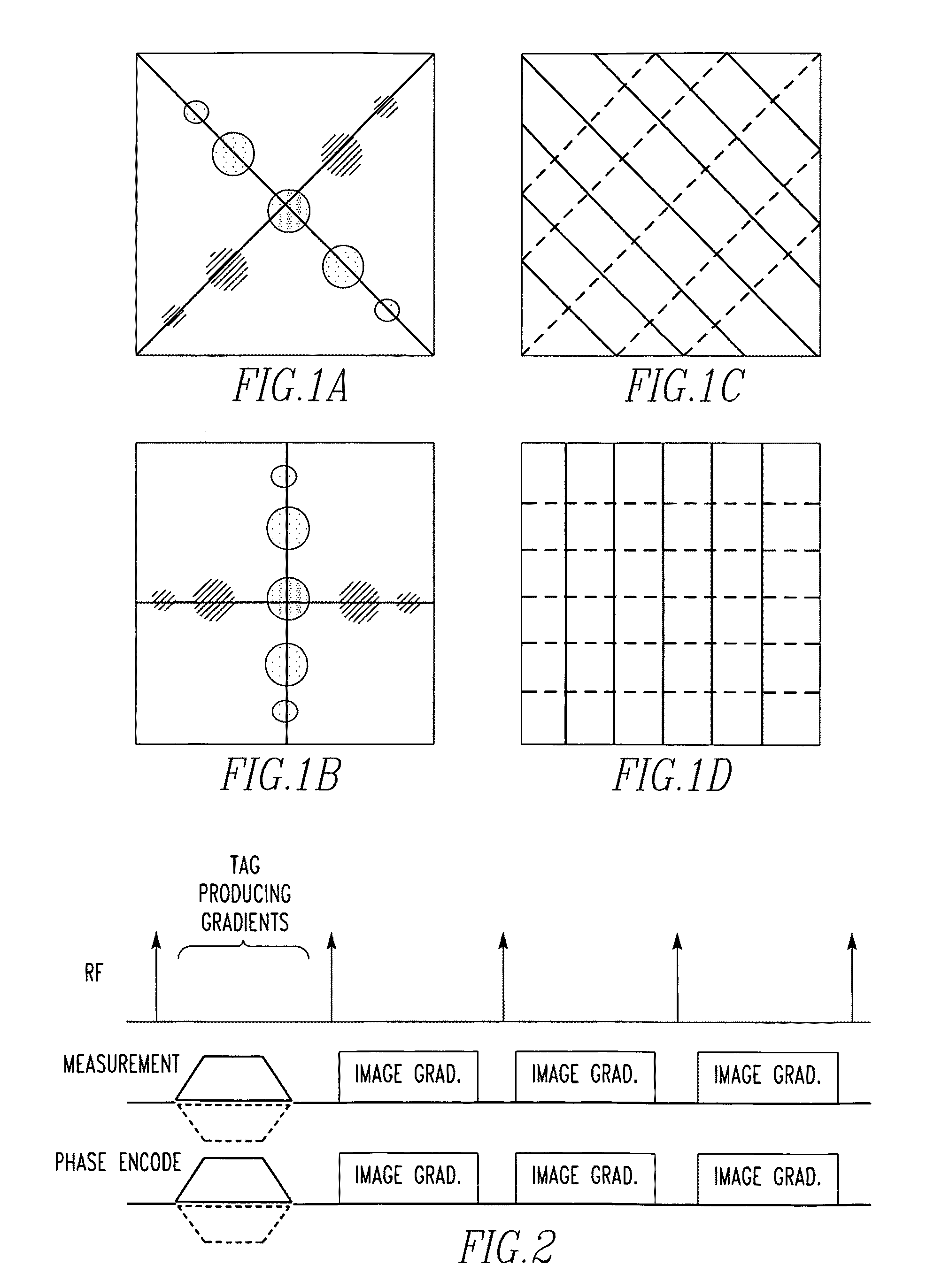
[0022]FIG. 10 shows k-space features of conventional gradient echo based tagging for conventional approach (upper panel) and the Common k-space approach (lower panel)

Problems solved by technology

However, due to the full echo acquisition of each signal read out, Common k-space could not be applied to tags at 45° without extending the scan time to 200% of the conventional scan time.
Thus, while there are similarities with previously described approaches, no other approach realized the acquisition characteristics for PRESSTO.
As the cardiac cycle progresses, the contrast-to-noise ratio (CNR) of the grid tag lines steadily deteriorates, such that during the diastolic period, the CNR of the grid tag lines is generally too poor to allow adequate tracking of diastolic recovery of the heart.
In this case, the two sets of stripe patterns destructively interfere with each other to further degrade the grid tag CNR.
This interruption to the steady state typically results in residual spurious signal that disrupt the following few lines of k-space, making this early data following application of the tag pattern un-useable.

Method used


Image

  • Magnetic resonance imager, method and program which continuously applies steady-state free precession to k-space
  • Magnetic resonance imager, method and program which continuously applies steady-state free precession to k-space
  • Magnetic resonance imager, method and program which continuously applies steady-state free precession to k-space

Examples


Embodiment Construction

[0025]Referring now to the drawings wherein like reference numerals refer to similar or identical parts throughout the several views, and more specifically to FIG. 12 thereof, there is shown a magnetic resonance imager 10 for forming images of a moving portion of a patient. The imager 10 comprises imaging coils 14. The imager 10 comprises a computer 12 that causes the imaging coils 14 to apply continuously steady-state free precession to k-space of a magnetic resonance image series of the patient and acquire the image series, and generates images from the image series.

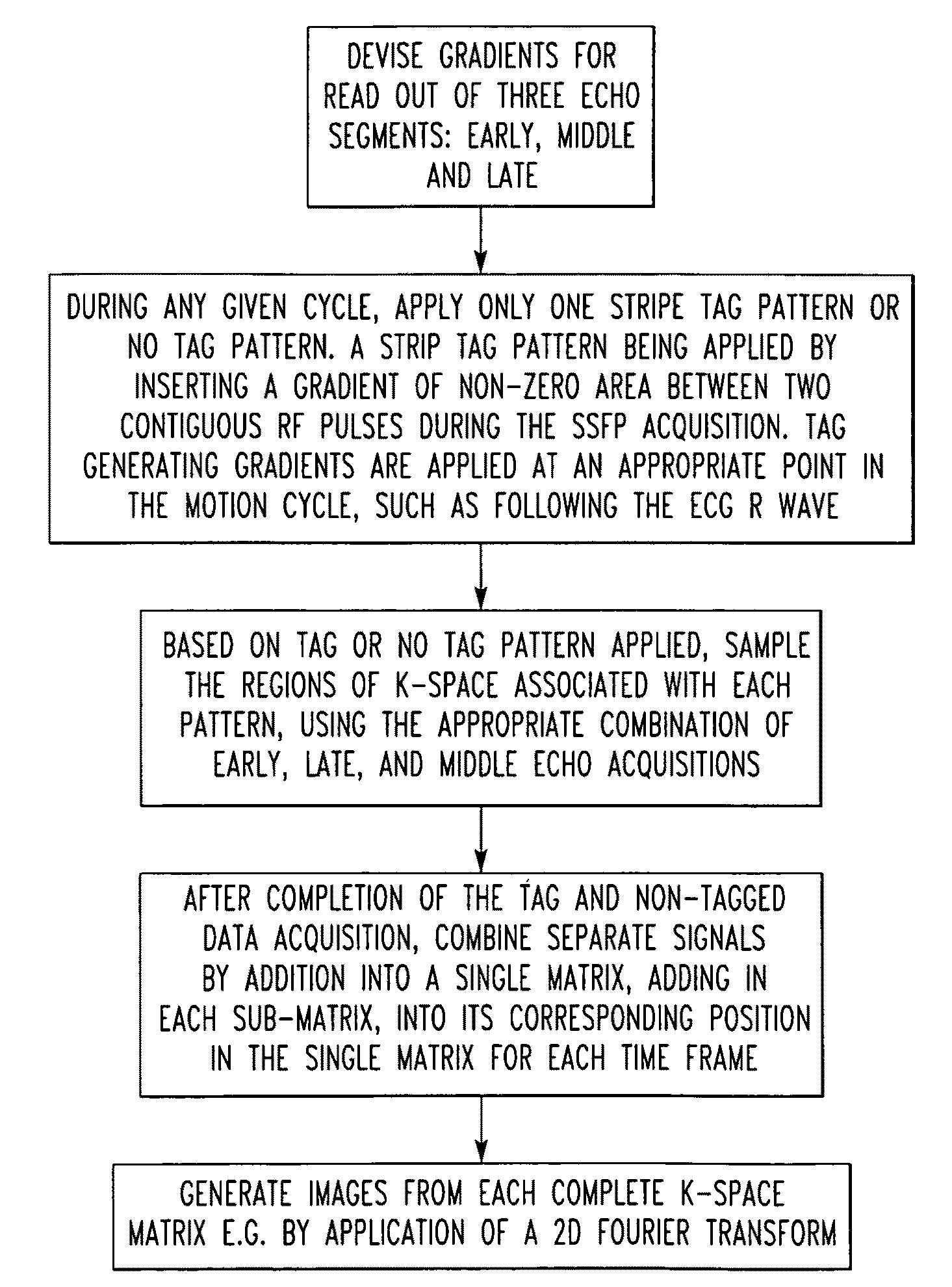
[0026]Preferably, the computer 12 causes the imaging coils 14 to apply a tag pattern to a motion cycle of the image series. The computer 12 preferably causes the imaging coils 14 to acquire the image series which shows the tag pattern deforming.

[0027]Preferably, wherein the computer 12 causes the imaging coils 14 to apply taglines in only one direction or no taglines during the cycle. The computer 12 preferably causes ...


PUM


Abstract

A magnetic resonance imager for forming images of a moving portion of a patient includes imaging coils. The imager includes a computer that causes the imaging coils to apply continuously steady-state free precession to k-space of a magnetic resonance image series of the patient and acquire the image series, and generates images from the image series. A method for forming images of a moving portion of a patient includes the steps of applying continuously steady-state free precession to k-space of a magnetic resonance image series of a patient. There is the step of acquiring the image series. There is the step of generating images from the image series. A method for forming images of a patient includes the steps of triggering a steady-state free precision imaging sequence to an ECG r wave of cardiac cycles of the patient. There is the step of performing the steady-state free precision imaging sequence with imaging coils of a magnetic resonance imaging scanner such that data for a series of k-space data sets associated with the imaging sequence are acquired in a manner that is time resolved through the cardiac cycle, with data acquired over a number of consecutive cardiac cycles. A computer program embodied on a computer readable medium to form an image of a patient with an MRI.

Description

FIELD OF THE INVENTION[0001]The present invention is related to forming imaging of a moving portion of a patient. (As used herein, references to the “present invention” or “invention” relate to exemplary embodiments and not necessarily to every embodiment encompassed by the appended claims.) More specifically, the present invention is related to forming imaging of a moving portion of a patient using steady-state free precession (SSFP) and a tag pattern in regard to k-space of a magnetic resonance imager.BACKGROUND OF THE INVENTION[0002]This section is intended to introduce the reader to various aspects of the art that may be related to various aspects of the present invention. The following discussion is intended to provide information to facilitate a better understanding of the present invention. Accordingly, it should be understood that statements in the following discussion are to be read in this light, and not as admissions of prior art.[0003]Others have applied tagging to SSFP ...

Claims


Application Information

Patent Timeline
IPC IPC(8): G01R33/483A61B5/055
CPCG01R33/5614G01R33/56333G01R33/56325G01R33/5616A61B5/055
Inventor DOYLE, MARKBIEDERMAN, ROBERT
Owner ALLEGHENY SINGER RES INST
Learn More