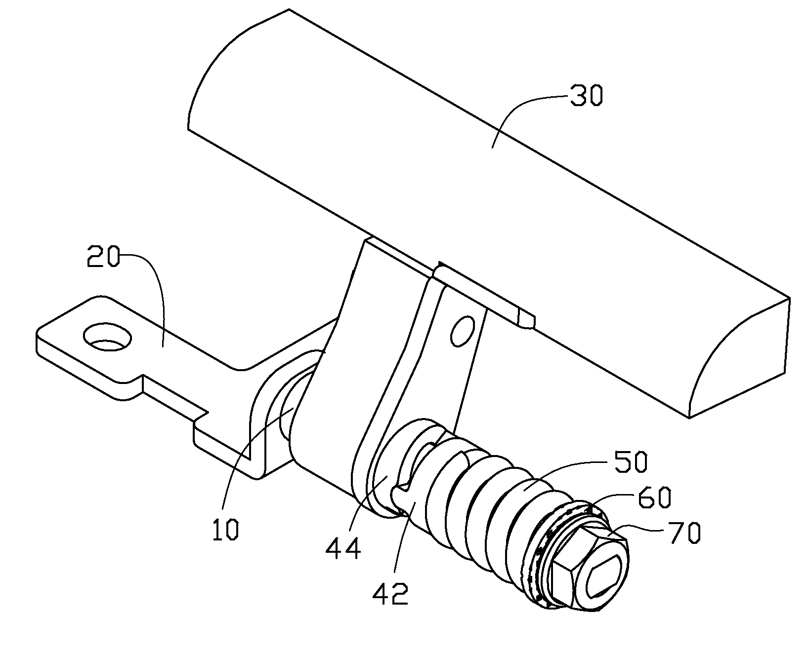
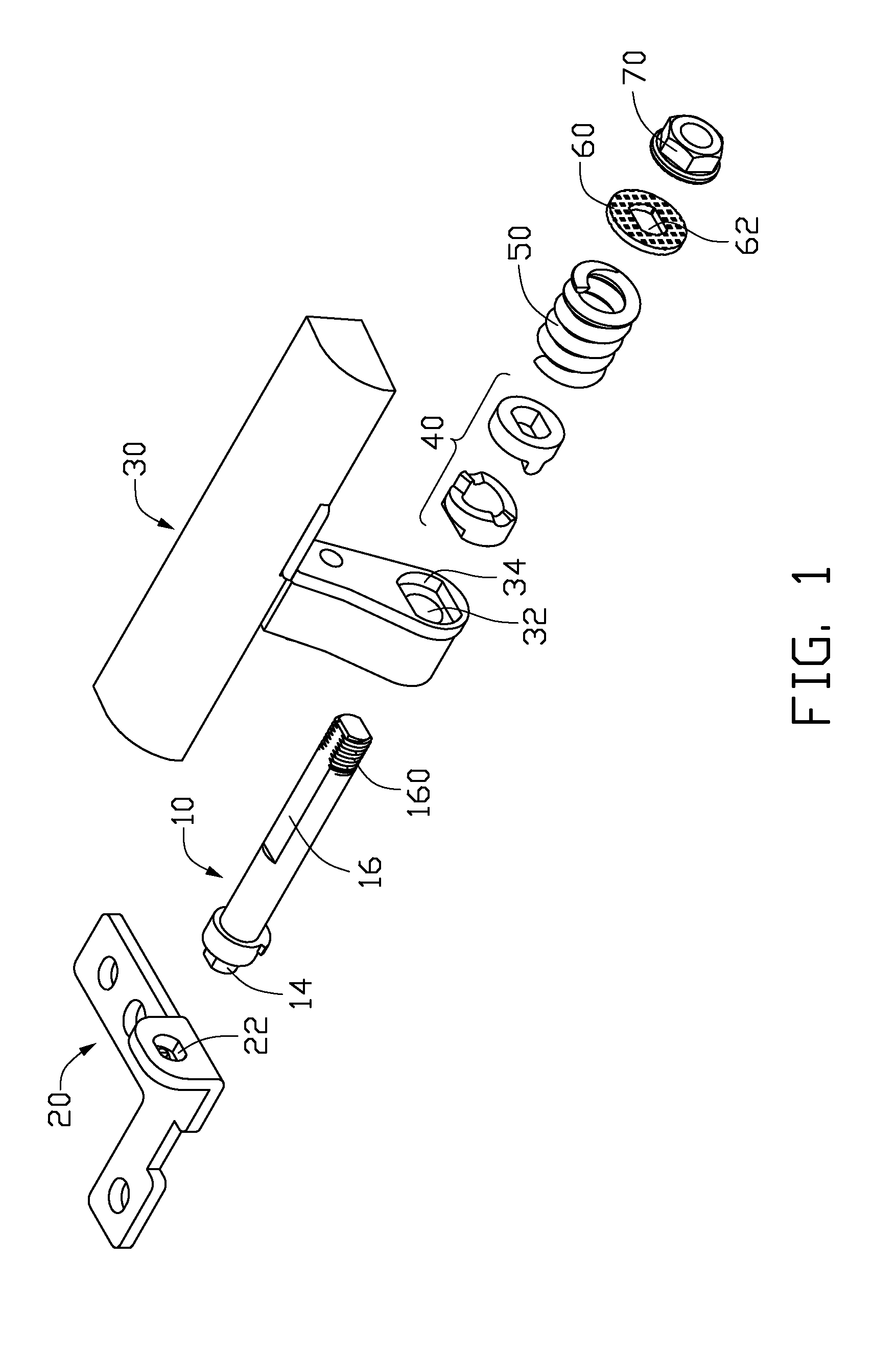
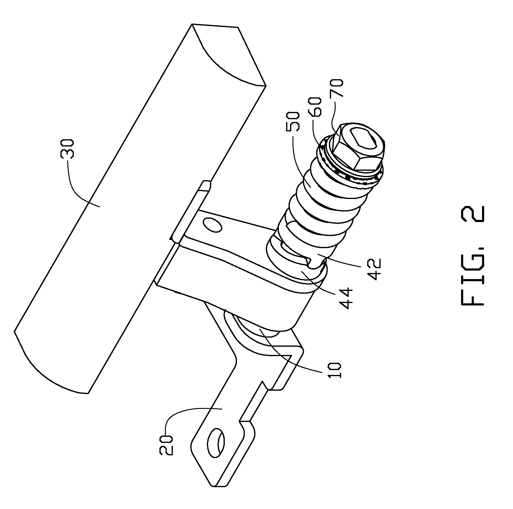
[0012]Referring to FIGS. 1 through 3, a hinge of an embodiment includes a shaft 10, a first bracket 20, a second bracket 30, an interference assembly 40, a resilient member 50, a washer 60, and a fastener 70. In this embodiment, the fastener 70 is a nut, and the resilient member 50 is a coil spring defining a through hole.
[0013]The shaft 10 includes a non-cylindrical conjoining portion 14, and a non-cylindrical post 16 opposite thereto. A distal end of the post 16 forms a threaded portion 160.
[0014]The first bracket 20 defines a non-circular fastening hole 22.
[0015]The second bracket 30 is T-shaped and defines a depressed portion 34 in a side of a lower part, facing the interference assembly 40. A circular through hole 32 is defined in the lower part of the second bracket 30, extending through a bottom of the depressed portion 34 and out the opposite side of the lower part.
[0016]The interference assembly 40 includes a first element 42, and a second element 44 engaging and rotating relative to the first element 42.
[0017]The first element 42 is generally cylindrical. The first element 42 defines a non-circular fixing hole 420 through the central portion of the first element 42. The fixing hole 420 extends through a first mating side 41 and out the opposite side, configured for snugly fitting about the non-cylindrical post 16 of the shaft 10. Two symmetrical fixing portions 424 perpendicularly extend from the first mating side 41. The fixing portions 424 are opposite to each other across the fixing hole 420.
[0018]The second element 44 is generally cylindrical. The second element 44 defines a circular through hole 440 through the central portion of the second element 44. The through hole 440 extends through a second mating side 45 and out the opposite side. The second mating side 45 faces the first mating side 41. The second mating side 45 defines a first fixing slot 442, and a second fixing slot 444 opposite to the first fixing slot 442 across the through hole 440. A first connecting portion 443 connected to one end of the first fixing slot 442 extends from the second mating side 45. A second connecting portion 446 extends from the second mating side 45, and connects to one end of the second fixing slot 444. The second fixing slot 442 is opposite to the first connecting portion 443. A first sliding portion 46 is formed on the second mating side 45, extending at an angle from the other end of the first fixing slot 442 towards the second connecting portion 446. The second connecting portion 446 includes a resisting surface 460, facing the first sliding portion 46. A second sliding portion 48 is formed on the second mating side 45, extending at an angle from the other end of the second fixing slot 444 towards the first connecting portion 443. The first connecting portion 443 includes a resisting surface 480, facing the second sliding portion 48. A mounting portion 49 extends from the side opposite to the second mating side 45 of the second element 44.
[0019]The washer 60 defines a non-circular through hole 62 through the center thereof, for snugly fitting about the post 16 of the shaft 10.
[0020]In assembly, the conjoining portion 14 of the shaft 10 is inserted into and fixed in the fastening hole 22 of the first bracket 20, such that the shaft 10 rotates together with the first bracket 20. The post 16 is passed though the through hole 32, the through hole 440, the fixing hole 420, the through hole of the resilient member 50, and the through hole 62 in turn, to engage with the fastener 70 via its threaded portion 160. The fastener 70 is configured for preventing the interference assembly 40, the resilient member 50, and the washer 60 from disengaging from the shaft 10. The first mating side 41 faces the second mating side 45. The mounting portion 49 of the second element 44 is inserted into and fixed to the depressed portion 34. One end of the resilient member 50 resists against the side opposite to the first mating side 41 of the first element 42, with the other end resisting against the washer 60.
[0021]Referring also to FIG. 4, in use, the second bracket 30 is fixed to a base 94 of a collapsible device 90, here a notebook computer. The first bracket 20 is fixed to a cover 92 of the collapsible device 90, and is synchronously rotatable with the cover 92 relative to the base 94.
[0022]Referring also to FIG. 5, when the cover 92 closes with the base 94, the fixing portions 424 of the first element 42 engage the first and second fixing slots 442, 444 of the second element 44, and the resilient member 50 is distorted.
[0023]Referring also to FIG. 6, when the cover 92 opens from the base 94, the first element 42 and the shaft 10 rotate with the cover 92. The first element 42 is rotated relative to the second element 44. Thereby, one of the fixing portions 424 is moved away from the first connecting portion 443. The other fixing portion 424 is moved away from the second connecting portion 446. When the fixing portions 424 are completely disengaged from the first and second fixing slots 442, 444, one of the fixing portions 424 is impelled along the first sliding portion 46, and the other fixing portion 424 is impelled along the second sliding portion 48. The resilient member 50 restores and moves the first element 42 towards the second element 44 fluidly and smoothly, enabling easy and trouble-free opening of the cover 92.
[0024]Referring also to FIG. 7, when the fixing portions 424 of the first element 42 resist the first and second resisting surfaces 460, 480 of the second element 44, the cover 92 cannot be rotated.
[0025]When closed, the cover 92 moves towards the base 94. One of the fixing portions 424 is moved upward along the first sliding portion 46 towards the first fixing slot 442. The other fixing portion 424 is moved upward along the first sliding portion 48 towards the second fixing slot 444. The first element 42 moves away from the second element 44 along an axis. As closing movement, one of the fixing portions 424 moves onto an edge of the first slot 442, and the other fixing portion 424 moves onto an edge of the second slot 444. At this point, the cover 92 may be physically released because the cover 92 can continue to rotate by force of inertia, but lightly so as not to impact the base 94. When the fixing portions 424 are completely engaged with the first and second fixing slots 442, 444, the cover 92 has closed on the base 94.
[0026]It is believed that the present embodiment and its advantages will be understood from the foregoing description, and it will be apparent that various changes may be made thereto without departing from the spirit and scope of the description or sacrificing all of its material advantages, the example hereinbefore described merely being an exemplary embodiment.