Dielectric barrier discharge apparatus and process for treating a substrate

a technology of dielectric barrier and discharge apparatus, which is applied in the direction of electric discharge lamps, chemistry apparatus and processes, plasma techniques, etc., can solve the problems of reducing yield, affecting the quality of substrates, so as to improve the reactivity and the effect of enhancing the ultraviolet production in the discharg

Inactive Publication Date: 2003-12-16
AXCELIS TECHNOLOGIES
View PDF13 Cites 61 Cited by
  • Summary
  • Abstract
  • Description
  • Claims
  • Application Information

AI Technical Summary

Benefits of technology

Although reference has been made to the use of atmospheric pressure, it has been unexpectedly found that increasing the pressure increases the reactivity. Moreover, the substrate may be heated during plasma processing to further increase the reactivity rate. The apparatus also produces UV radiation, which can have a variety of effects on both the gas within the c...

Problems solved by technology

A large majority of these plasma generators require vacuum systems that operate at about 1 to about 10 torr and employ sophisticated, expensive plasma sources such as microwave plasma generators as used in many downstream plasma ashers, radio frequency(rf) plasma generators, combinations comprising at least one of the foregoing plasma sources, and the like.
However, atmospheric plasma tools are generally limited in spatial extent(on the order of a few centimeters) requiring various techniques such as wafer rotation or scanning of the plasma source to overcome this limitation and provide uniform ashing.
The use of bare electrodes inevitably introduces particles that can deleteriously compromise the integrity of the circuits produced on the wafers.
Additionally, the electrical currents (DC or AC) may damage the devices being manufactured on the substrate, e.g., wafer, causing lower yields.
In either scenario, the discharges generated by the dielectric discharge barrier apparatus pass through the wafer, thereby damaging the circuitry previously formed in the wafer or causing localized variations in the ashing rate.
However, the apparatus cannot be scaled to large dimensions since the insulating cylinder must remain thin because it is required to conduct the radio frequency discharge current.
Further, the dielectric material is subject to attack by the reactive gases, and introduces a phase lag, which requires that higher voltages and lower currents must be employed to maintain the disch...

Method used


Image

  • Dielectric barrier discharge apparatus and process for treating a substrate
  • Dielectric barrier discharge apparatus and process for treating a substrate

Examples


Embodiment Construction

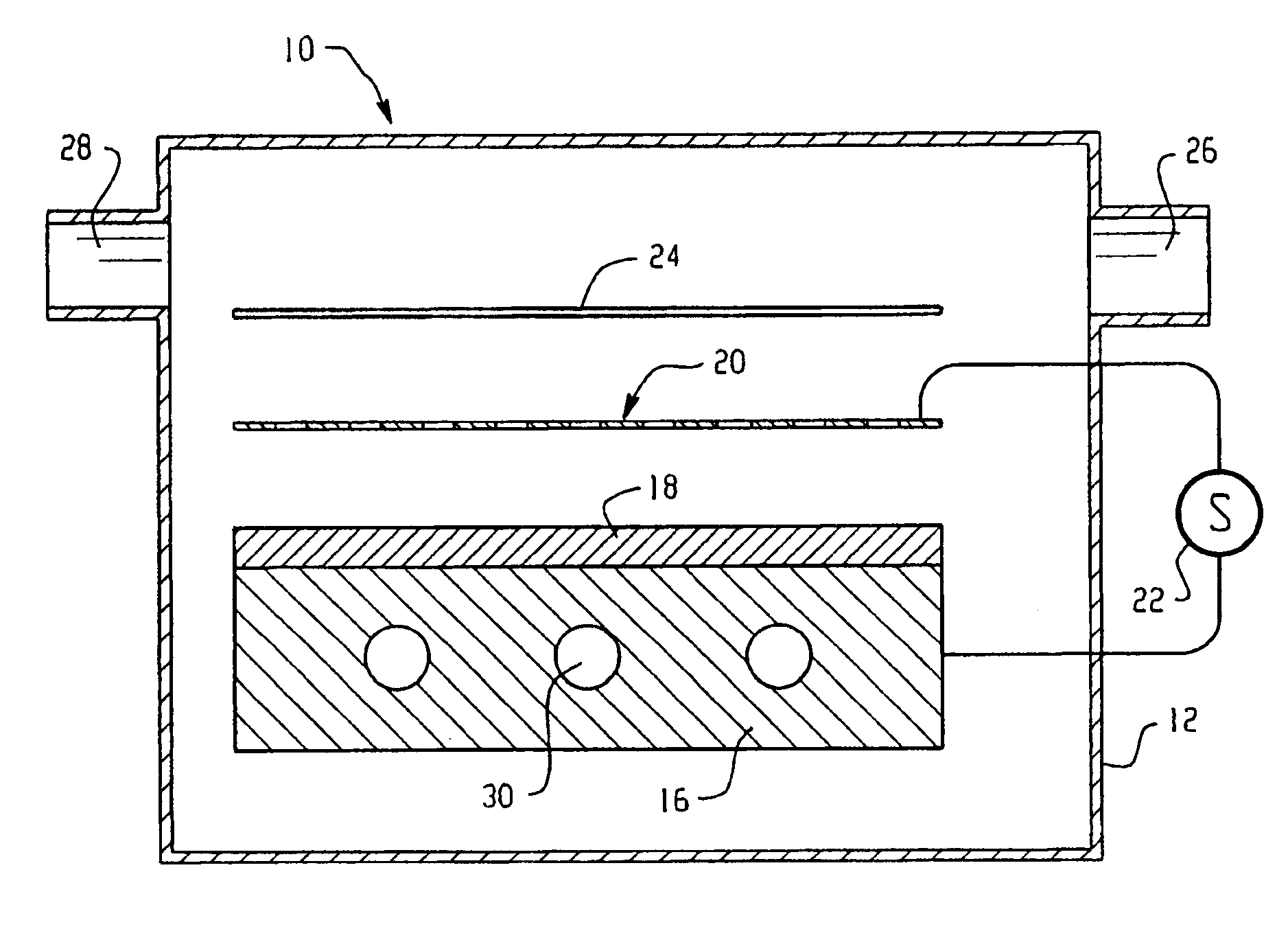
In this example, the apparatus of FIG. 1 was employed to treat a substrate having a 2.4 microns thick photoresist layer coated thereon. The substrate was oriented such that the photoresist layer was facing the screen electrode at a distance of 2 mm from the screen electrode. The distance between the screen electrode and the dielectric layer was 1.6 millimeters. The screen electrode was chosen to have a geometric transmission factor of about 92% and was supported at each corner and held in a parallel plane with the dielectric layer. The dielectric layer was fabricated from a thin sheet of quartz glued to the base electrode, and ground and polished to a final thickness of 0.38 mm. Power input to the electrodes was less than about 25 watts. Ambient air at about atmospheric pressure was introduced into the chamber.

An ozone detector was positioned above the screen electrode during operation in an area unimpeded by the substrate and at a similar distance as the substrate. The ozone detect...


PUM

PropertyMeasurementUnit
Lengthaaaaaaaaaa
Fractionaaaaaaaaaa
Fractionaaaaaaaaaa

Abstract

A dielectric barrier discharge apparatus for treating a substrate includes a first planar electrode; a dielectric layer disposed on a surface of the first planar electrode; a porous planar electrode spaced above and in a parallel plane with the dielectric layer, wherein the porous planar electrode has a geometric transmission factor greater than 70 percent; and a power supply in electrical communication with the first electrode and the second electrode. A process for treating a substrate includes exposing the substrate surface to reactants produced by the dielectric barrier discharge apparatus.

Description

BACKGROUND OF INVENTIONThe present disclosure relates to a reactor assembly for processing substrates and more particularly, to a distribution system for flowing gases and / or reactants into and out of the reactor assembly process and apparatus for treating a substrate and, more particularly, to a dielectric barrier discharge apparatus and processes for treating a surface of the substrate.Plasmas and plasma generation have been studied for many years. There are several types of plasma generators currently employed for numerous applications. A large majority of these plasma generators require vacuum systems that operate at about 1 to about 10 torr and employ sophisticated, expensive plasma sources such as microwave plasma generators as used in many downstream plasma ashers, radio frequency(rf) plasma generators, combinations comprising at least one of the foregoing plasma sources, and the like.Other types of plasma generators are designed to operate at atmospheric pressures, which avo...

Claims


Application Information

Patent Timeline
IPC IPC(8): H01J37/32H01L21/3065H05H1/24
CPCH01J37/32009
Inventor BERRY, IVANJANOS, ALAN C.COLSON, MICHAEL BRUCE
Owner AXCELIS TECHNOLOGIES
Why Eureka
Try Eureka