Dynamic performance monitoring of long slender structures using optical fiber strain sensors

Inactive Publication Date: 2007-10-02
WILLIAMS JERRY GENE
View PDF12 Cites 65 Cited by
  • Summary
  • Abstract
  • Description
  • Claims
  • Application Information

AI Technical Summary

Benefits of technology

[0027]It is therefore an object of the invention to provide a capability through multiplexing of the Optical Time Domain Reflectometry (OTDR) and Bragg Diffraction instrumentation to allow numerous optical fibers or multiple reflections within the same fiber to be monitored using a single or multiple instruments.
[0028]In accordance with the present invention, there is provided a method for in situ measurement of the bending strain of metal and composite tubulars located in the marine environment using optical fiber techniques including Optical Time Domain Reflectometry (OTDR) or Bragg diffraction gratings. The method uses these rapidly obtained bending strain measurements to determine the dynamic characteristics of long slender structure or to determine the spiral buckle characteristics and pending state of lock-up in spoolable pipe deployed into a small diameter annulus. The method provides the capability to determine the local bending strain along the length of the structure caused by wind or water induced disturbances and through engineering analysis to determine structural dynamic response characteristics including the vibration frequency, vibration peak amplitude, and periodic node to node wave length. For example, one can use the method to determine the vibration characteristics of offshore risers subjected to Vortex Induced

Problems solved by technology

Deepwater presents many new challenges with the design of long slender structures such as marine risers in which the length of the structure is significantly greater than the other two dimensions.
Marine rises are especially susceptible to the potentially damaging effects of dynamic disturbances such as Vortex Induced Vibrations (VIV).
As the water depth of exploration and production operations has increased, so has the challenge imposed on the design and reliability of risers and other long slender structures subjected to vibrations induced by water and wind induced loads.
Corrosion or damage can occur and VIV can impose excessive stress and fatigue damage.
The capability to inspect and monitor long slender structure dynamic performance has therefore become an important technology issue; particularly when the inspection must be conducted in situ.
The composites and oil industry have supported research and development on composite risers for over twenty years and although many believe the technology is ready for deployment, the expectation has not yet been fulfilled except in isolated trial deployments.
Probably the most important factor limiting the acceptability of this needed service is the reluctance of regulatory agencies to approve introduction of such safety critical component without the accompaniment of reliable methods for inspection.
Although metal components have establis

Method used


Image

  • Dynamic performance monitoring of long slender structures using optical fiber strain sensors
  • Dynamic performance monitoring of long slender structures using optical fiber strain sensors
  • Dynamic performance monitoring of long slender structures using optical fiber strain sensors

Examples


Embodiment Construction

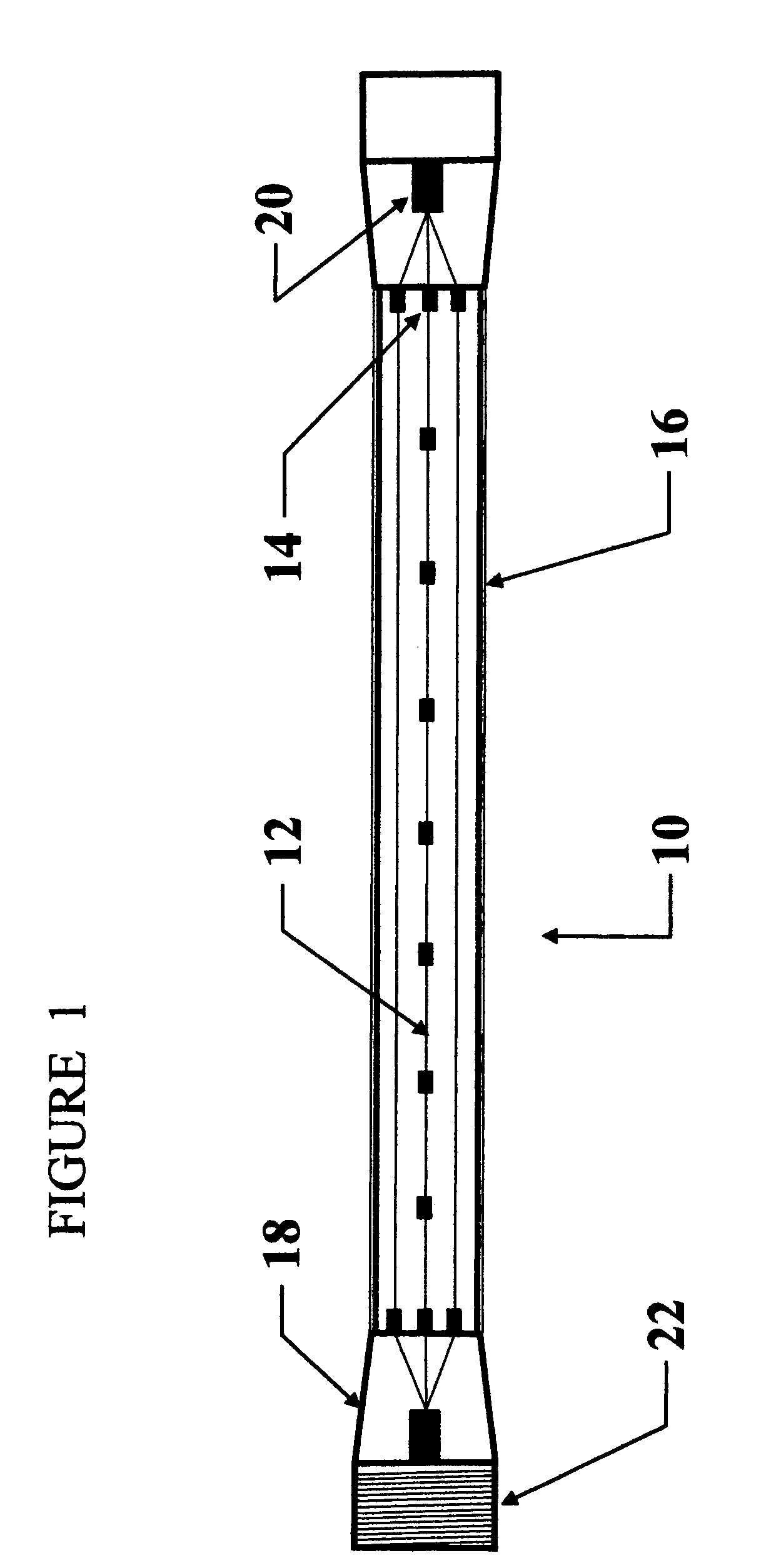
[0034]Now referring to FIG. 1, which is a side view of a Long Slender Metal or Composite Structure 10 indicating the positioning of fiber optics apparatus required to provide strain measurements. The Long Slender Metal or Composite Structure 10 is a single segment of a long assembly of similar structures joined together with Threaded End Coupling 22 located on End Termination 18 or by other means. Axial Optical Fibers 12 are positioned along the axis of the Long Slender Metal or Composite Structure 10 and the glass or plastic optical fibers have Optical Reflective Interfaces 14 to provide capabilities consistent with either time of flight instrumentation such as Optical Time Domain Reflectometry or as gratings for Bragg diffraction strain measurements. Optical Reflective Interface 14 may be placed at each end of the optical fiber which is rigidly attached to the long slender structure making possible a gage length of the entire length of the Long Slender Metal or Composite Structure...


PUM


Abstract

A method is described using optical fiber technology to measure the vibration characteristics of long slender structures subjected to dynamic disturbances imposed by water or wind generated loads. The method is based on making bending strain measurements at selected locations along the length of long slender structures such as marine risers or large ropes using fiber optics technology including Optical Time Domain Reflectometry and Bragg diffraction gratings. Engineering interpretation of information obtained from bending strains determines the vibration characteristics including frequency, amplitude, and wave length. Maximum bending strain measurements assess pending structural damage. One application is measurement of vortex induced vibrations (VIV) response of marine risers. The fiber optics based method is also applicable to the measurement of the bending characteristics of spoolable pipe using plastic optical fibers which can be interpreted to assess the pipe structural integrity and to prevent lock-up during deployment into a small diameter annulus.

Description

DESCRIPTION[0001]This application claims priority from U.S. Provisional Patent Application No. 60 / 441,703, filed Jan. 23, 2003 entitled “Fiber Optics Strain Measurement On Composite Tubulars”, herein incorporated by reference in the entirety.FIELD OF THE INVENTION[0002]The present invention relates to a fiber optics system which provides the capable to measure in situ the vibration characteristics of long slender structures excited by dynamic disturbances imposed by water or wind generated loads. Long slender structures include, but are not limited to composite or metal risers and tubing used in offshore petroleum industry drilling and production operations and large ropes and cables. For example, the method can be used to measure the magnitude, period, and frequency of Vortex Induced Vibrations (VIV) of risers used in offshore petroleum drilling and production operations; and more particularly, through engineering interpretation of the bending strain data to predict the fatigue lif...

Claims


Application Information

Patent Timeline
IPC IPC(8): G01B11/16G01L1/00G01L1/24
CPCE21B47/0006G01L1/246E21B47/01E21B47/007
Inventor WILLIAMS, JERRY GENE
Owner WILLIAMS JERRY GENE
Why Eureka
Try Eureka