Steering column device

a technology of steering column and steering lock, which is applied in the direction of steering column, vehicle mounted steering control, transportation and packaging, etc., can solve the problems of inadequate rigidity of steering locking by steering lock device, reducing the rigidity and strength of the outer column itself, etc., and achieves small variation in the force required to operate the operation lever. , the effect of increasing the rigidity and strength of the outer column

Active Publication Date: 2010-01-07
NSK LTD
View PDF11 Cites 30 Cited by
  • Summary
  • Abstract
  • Description
  • Claims
  • Application Information

AI Technical Summary

Benefits of technology

[0021]In a steering column device according to the present invention, a reinforcement part formed at a peripheral edge of a slit formed in an outer column, while increasing the rigidity and strength of the outer column, makes it possible to elastically deform with ease the outer column in its slit portion and securely clamp an inner column. In a case where the steering lock device has a structure which can include a steering lock device, the strength of steering locking by the steering lock device increases.
[0022]In a steering column device according to the present invention, both ends of a slit are closed, and a cut is formed in at least one of the closed end sections of the slit. Therefore, the variation in the force required to operate an operation lever is small, and the force required to elastically deform an outer column is also small. As a result, the force required to operate the operation lever can be held small.
[0023]Furthermore, in a steering column device according to the present invention, a contact area between side plates of a body side upper bracket and a clamp portion of an outer column is changed according to a telescopic position of the outer column, thereby changing the bending moment applied to the clamp portion. This makes it possible to reduce the difference in the force required to elastically deform the outer column in its slit portion between when the telescopic position is toward the vehicle front and when the telescopic position is toward the vehicle rear.

Problems solved by technology

Whereas such a steering column device having a slit formed in an outer column is advantageous in that the outer column can be elastically deformed in its slit portion with ease to securely clamp an inner column, it has a problem that the slit decreases the rigidity and strength of the outer column itself.
Particularly, in cases where the steering column device has a structure which allows a steering lock device to be attached to the outer column, the rigidity of steering locking by the steering lock device becomes inadequate.

Method used


Image

  • Steering column device
  • Steering column device
  • Steering column device

Examples


first embodiment

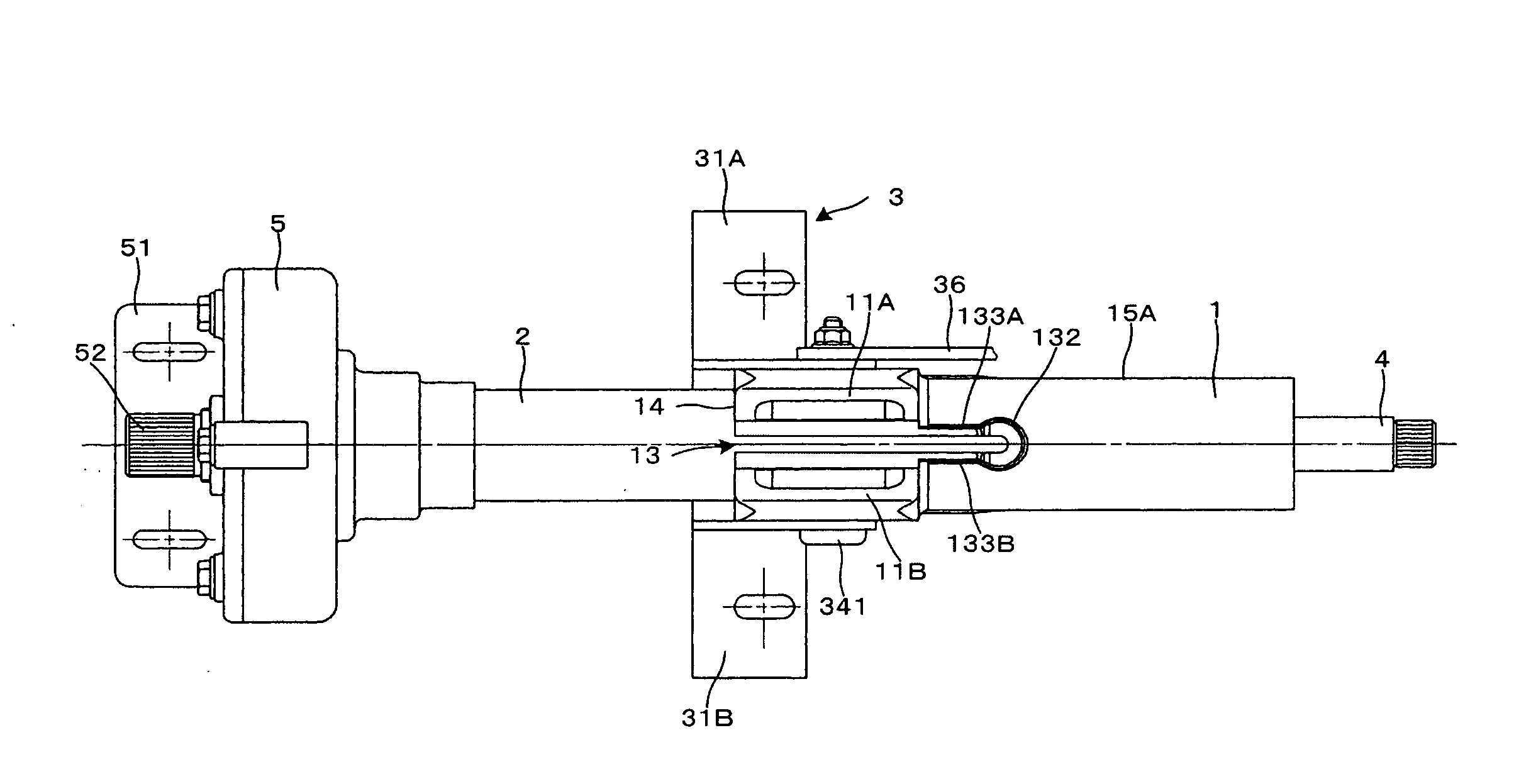
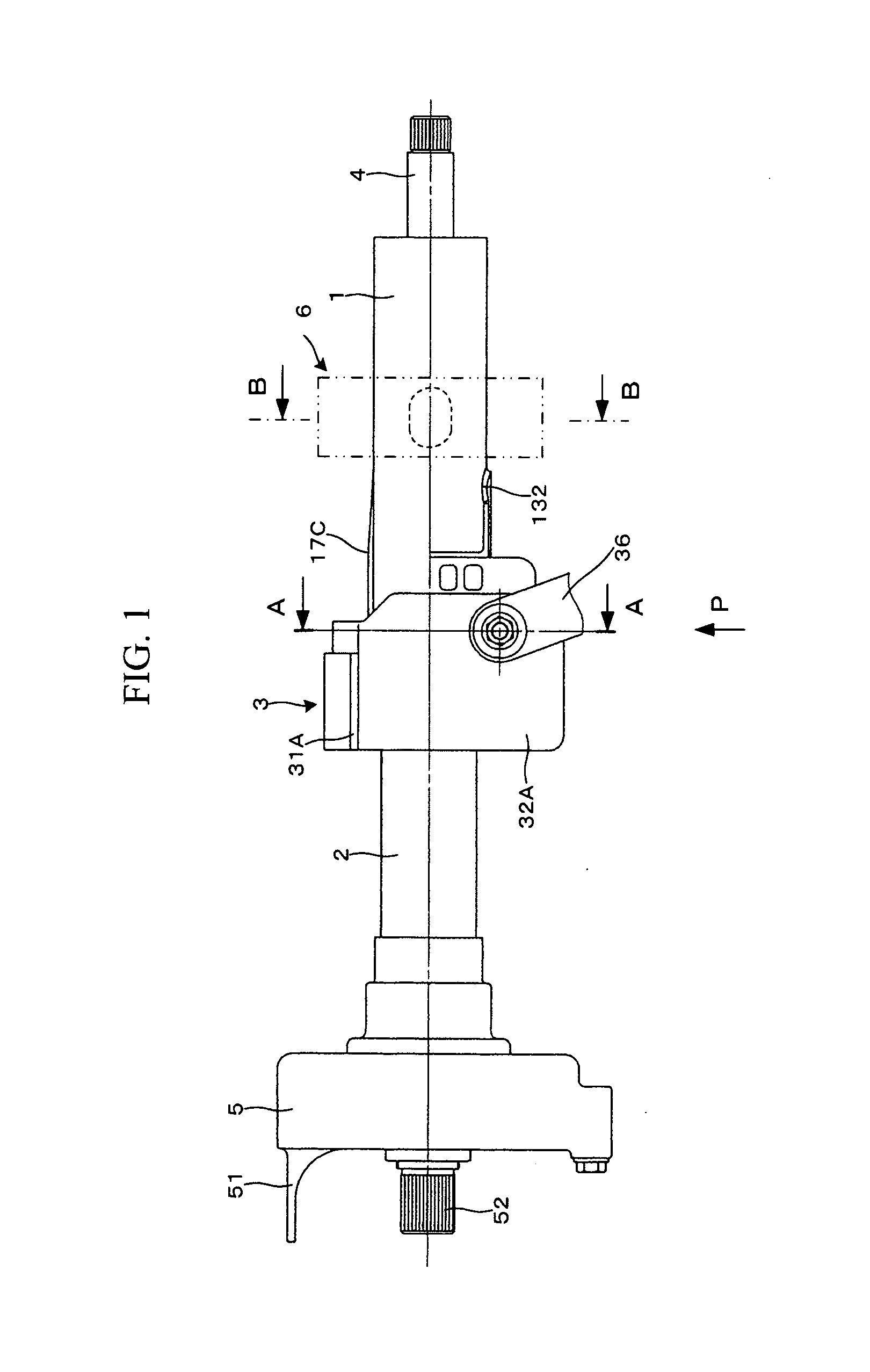
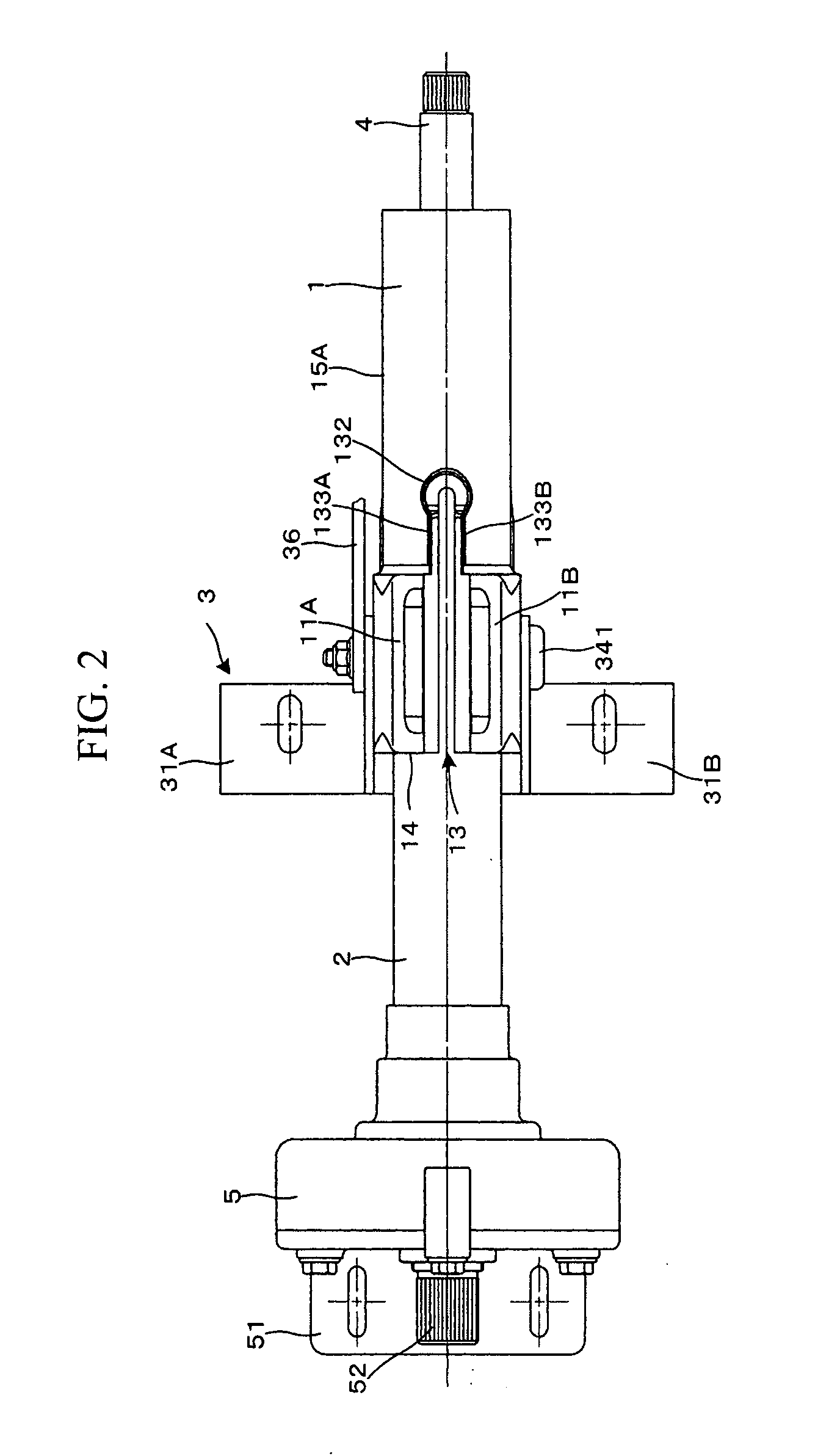
[0103]Trying to forcefully turn the steering wheel when the steering is locked causes the outer column 1 to be subjected to a torsional torque about its axis. The outer column 1 is also enhanced in terms of torsional rigidity and bending rigidity required to withstand such a torsional torque. Even though, in the first embodiment, the inner column 2 is axially slidably fitted to the outer column 1 on the vehicle front side, the inner column 2 may be axially slidably fitted to the outer column 1 on the vehicle rear side.

[0104]FIG. 8 is an overall side view of a steering column device according to a second embodiment of the present invention. The steering column device according to the second embodiment of the present invention is provided with no electric power steering device. In the following description of the steering column device of the second embodiment, only the portions structured differently from the first embodiment will be covered, and description already made in connectio...

third embodiment

[0107]The steering column device of the third embodiment includes a substantially semi-circular arc patch 134 welded to the peripheral edge of a closed end section 131 of a slit 13. The semi-circular arc patch 134 reinforces the closed end section 131 where stress most concentrates, and thereby increases the rigidity and strength of the outer column 1. The patch 134 may be welded to an inner peripheral surface 15B of the outer column 1.

[0108]FIG. 10 is a bottom view of an outer column alone of a steering column device according to a fourth embodiment of the present embodiment. As is the case with the third embodiment, the outer column 1 of the fourth embodiment is also formed out of a hollow cylindrical steel pipe. In the following description of the steering column device of the fourth embodiment, only the portions structured differently from the above embodiment will be covered, and description already made in connection with the above embodiment will not be repeated.

fourth embodiment

[0109]In the steering column device of the fourth embodiment, a slit 13 has a semi-circular arc closed end section whose diameter D1 is larger than the width W of an open end section 136 as well as a parallel section 137. Enlarging the width of the closed end section 135 where stress concentrates most reduces the concentration of stress there, and increases the rigidity and strength of the outer column 1.

[0110]FIGS. 11(1) to 11(3) show an outer column alone of a steering column device according to a fifth embodiment of the present invention. FIG. 11(1) is a bottom view. FIG. 11(2) is a cross-sectional view taken along line D-D in FIG. 11(1). As is the case with the third and fourth embodiments, the outer column 1 of the fifth embodiment is also formed out of a hollow cylindrical steel pipe. In the following description of the steering column device of the fifth embodiment, only the portions structured differently from the above embodiments will be covered, and description already ma...


PUM

PropertyMeasurementUnit
axial lengthaaaaaaaaaa
areaaaaaaaaaaa
distanceaaaaaaaaaa

Abstract

A steering column device where an inner column can be reliably clamped and sufficient rigidity and strength of an outer column can be achieved. A semi-circular arc rib (132) is formed on the peripheral edge of a closed end section (131) of a slit (13). The rib (132) is substantially semi-circular are-shaped and projects outward from an outer peripheral surface (15A) of an outer column (1). Further, linear ribs (133A, 133B) extend linearly toward the vehicle body front side so as to be continuous from the vehicle body front side of the semi-circular arc rib (132). The semi-circular arc rib (132) and the linear ribs (133A, 133B) reinforce the peripheral edge of the slit (13) of the outer column (1) whose rigidity and strength are impaired. Thus the rigidity and strength of the outer column (1) are improved.

Description

TECHNICAL FIELD[0001]The present invention relates to a steering column device, particularly, one which adjusts a telescopic position of a steering wheel using an outer column and an inner column axially slidably fitted together and which, at a time of secondary collision, moves by collapsing so as to absorb a shock load.BACKGROUND ART[0002]A steering column device has been known in which an outer column and an inner column are axially slidably fitted together allowing a telescopic position to be adjusted and, at a time of secondary collision, a shock load to be absorbed. Generally, in such a steering column device, an axial slit is formed in the outer column; and the outer column is clamped from its outer periphery causing the outer column to be elastically deformed in its slit portion, so that, when the vehicle is in normal operation, the inner column is clamped to be unmovable relative to the outer column (Patent Document 1).[0003]Whereas such a steering column device having a sl...

Claims


Application Information

Patent Timeline
Patent Type & Authority Applications(United States)
IPC IPC(8): B62D1/185
CPCB62D1/184B22D17/00B62D1/185
Inventor NOMURA, TETSUOYAMADA, JUN
Owner NSK LTD
Why Eureka
Try Eureka