Air atomizing type coating apparatus

Active Publication Date: 2010-01-07
ABB (SCHWEIZ) AG
View PDF6 Cites 19 Cited by
  • Summary
  • Abstract
  • Description
  • Claims
  • Application Information

AI Technical Summary

Benefits of technology

[0036]In this case, when a feed tube of a paint cartridge is placed into each feed tube passage hole, its fore end is advanced to fit in the third feed tube passage hole in the projection tube provided on the valve case. Accordingly, paint in the paint cartridge can be discharged from the projection tube to the paint nozzle without l

Problems solved by technology

That is to say, on a color change, a large amount of paint has to be wastefully discarded, in addition to the necessity for a time-consuming washing operation involving consumption of large amounts of wash fluids.
However, as compared with a direct charging

Method used


Image

  • Air atomizing type coating apparatus
  • Air atomizing type coating apparatus
  • Air atomizing type coating apparatus

Examples


Example

[0055]Referring first to FIGS. 1 through 14, there is shown a first embodiment of the present invention. In this first embodiment, by way of example the invention is applied to a coating apparatus using aqueous paint which solvent of paint is water and employing water and air as wash fluids.

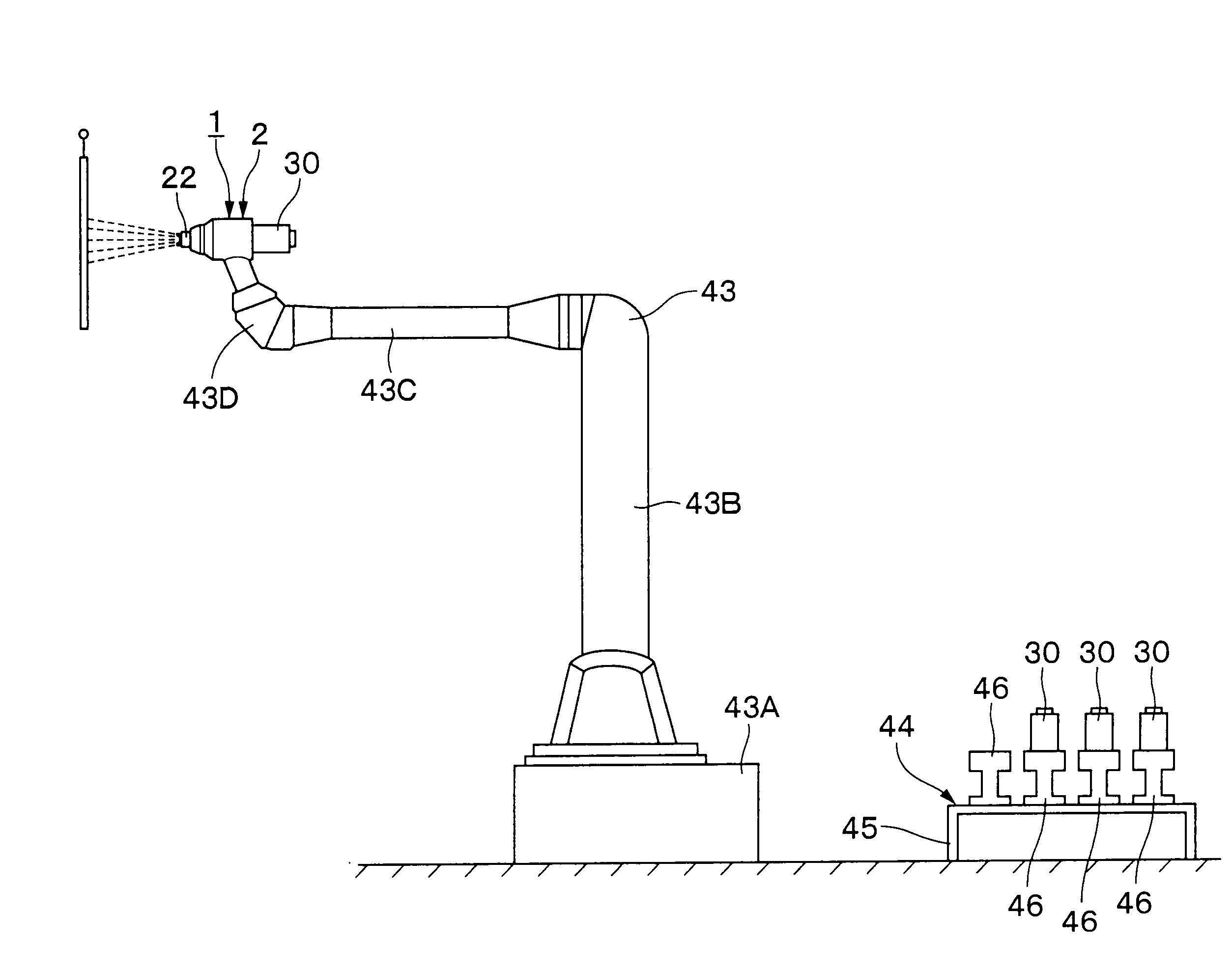
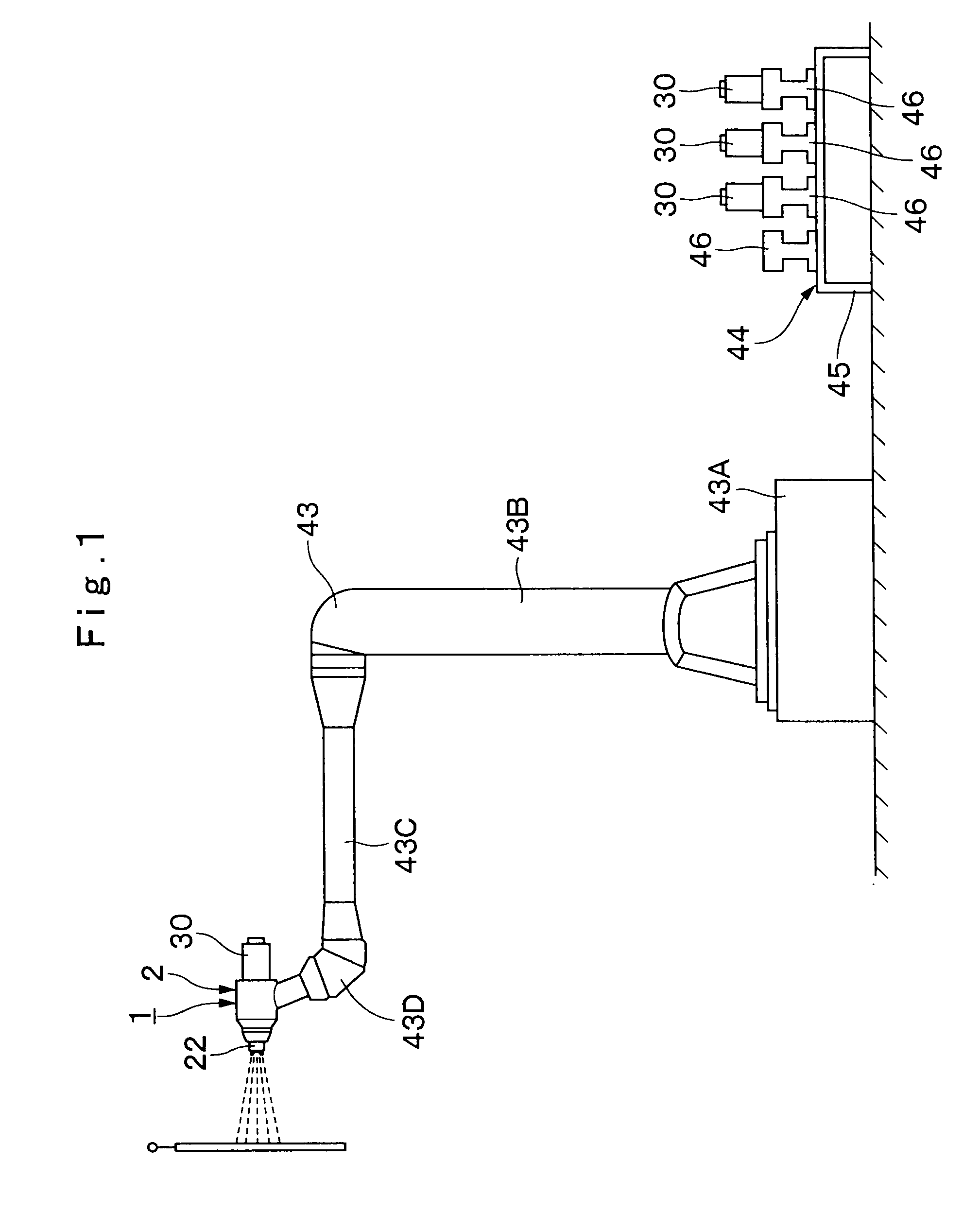
[0056]In FIG. 1, indicated at 1 is an air atomizing type paint coating apparatus (hereinafter simply referred to as “coating apparatus” for brevity) in a first embodiment of the invention. This coating apparatus 1 is of the air spray type which is adapted to atomize and spray paint by means of blasts of atomizing air, and attached on a coating robot 43, which will be described hereinafter. Further, the coating apparatus 1 is interchangeably loaded with one of paint cartridges 30 which will be described hereinafter, and built as an electrostatic coating apparatus of direct charging method which is capable of applying a high voltage directly to circulating paint. As shown in FIG. 2, the coating app...

Example

[0138]Now, turning to FIG. 15, there is shown a second embodiment of the present invention. This embodiment has a feature in abolishment of a wash fluid passage change-over valve. In the following description of the second embodiment, those component parts which are identical with a counterpart in the foregoing first embodiment are simply designated by the same reference numeral or character to avoid repetitions of similar descriptions.

[0139]In FIG. 15, indicated at 51 is an air atomizing type paint coating apparatus 1 (hereinafter simply referred to as “coating apparatus” for brevity) in a second embodiment of the invention. The coating apparatus 51 of this embodiment is provided with a single wash fluid passage 52 instead of the wash fluid passage change-over valve 19 in the first embodiment. Namely, the coating apparatus 51 of the second embodiment differs from that of the first embodiment in that it is arranged to connect the wash fluid selector valve 38 with the passage change-...


PUM


Abstract

There is provided an air atomizing type coating apparatus which is constituted by a main body (2) having a first feed tube passage hole (6) extended forward from a cartridge mount portion (5), a passage change-over mechanism (11) attached to the front side of the main body (2) to change over positions of a second feed tube passage hole (14) and a second wash fluid passage (15), a spray nozzle (22) attached on the front side of the passage change-over mechanism (11), and a paint cartridge (30) to be set in the cartridge mount portion (5). Upon shifting the passage change-over mechanism (11) to a coating position, the first and second feed tube passage holes (6) and (14) are brought into communication with each other, a coating operation can be performed by inserting a paint cartridge (30). On the other hand, upon shifting the passage change-over mechanism (11) to a washing position, the first and second wash fluid passages (9) and (15) are brought into communication with each other, permitting a supply of a wash fluid to the spray nozzle (22).

Description

TECHNICAL FIELD[0001]This invention relates to an air atomizing type coating apparatus which performs coating by atomizing paint spurted out from a paint nozzle by air spurted out from an air nozzle.BACKGROUND ART[0002]Generally, for painting broad surface areas of a work piece such as vehicle body, furniture and electric appliance, it is the usual practice to use a rotary atomizing head type coating apparatus which can cope with large spray patterns. On the other hand, for painting small surfaces with minute ups and downs, it is often the case to resort to a pneumatic atomization or air atomizing type coating apparatus (an air spray gun) which is capable of spraying paint particles with high directionality in a straightforward direction.[0003]An air atomizing type coating apparatus of this sort is largely constituted by a main body to be attached on a fore end portion of an arm of a coating robot or to be held in an operator's hand, an air atomizing type paint atomizing means attac...

Claims


Application Information

Patent Timeline
IPC IPC(8): B05B7/14
CPCB05B1/3026B05B5/1691B05B15/025B05B12/1463B05B7/066B05B15/55B05B1/302
Inventor ONDA, TOSHIO
Owner ABB (SCHWEIZ) AG
Why Eureka
Try Eureka