Supercharge Your Innovation With Domain-Expert AI Agents!

Cursor control device

a control device and cursor technology, applied in the field of cursor control devices, can solve the problems of complicated operating methods, inapplicability, and failure to operate normally the cursor control device, and achieve the effect of preventing the user from using the air mouse, and preventing the user from using the mous

Inactive Publication Date: 2010-01-07
AVER INFORMATION INC
View PDF11 Cites 7 Cited by
  • Summary
  • Abstract
  • Description
  • Claims
  • Application Information

AI Technical Summary

Benefits of technology

[0012]In an embodiment, the cursor control device further includes several command input keys having respective light sources and light guide structures. The light source of the command input key which is depressed emits a light beam. The light beam is guided by the corresponding light guide structure to light up the periphery of the depressed command input key.

Problems solved by technology

If the first and second cursor control devices are not contacted with the working plane, such cursor control devices fail to be normally operated and thus are not applicable in the situation when the user is moved from a place to another place.
Since the gyroscope module of the air mouse senses rotation of the joint of the human's arm to generate corresponding cursor movement in the coordinate system, the complicated operating method becomes hindrance from using the air mouse, particularly for the uneducated users.
Consequently, the third cursor control device is not popular.
Moreover, the gyroscope module is very sensitive to temperature variations and thus difficult to be subject to mass production.
In cooperation with a G-sensor and firmware, the applications of the gyroscope module are expanded but the extra components increase the fabricating cost.

Method used


Image

  • Cursor control device
  • Cursor control device
  • Cursor control device

Examples


Embodiment Construction

[0019]The present invention will now be described more specifically with reference to the following embodiments. It is to be noted that the following descriptions of preferred embodiments of this invention are presented herein for purpose of illustration and description only. It is not intended to be exhaustive or to be limited to the precise form disclosed.

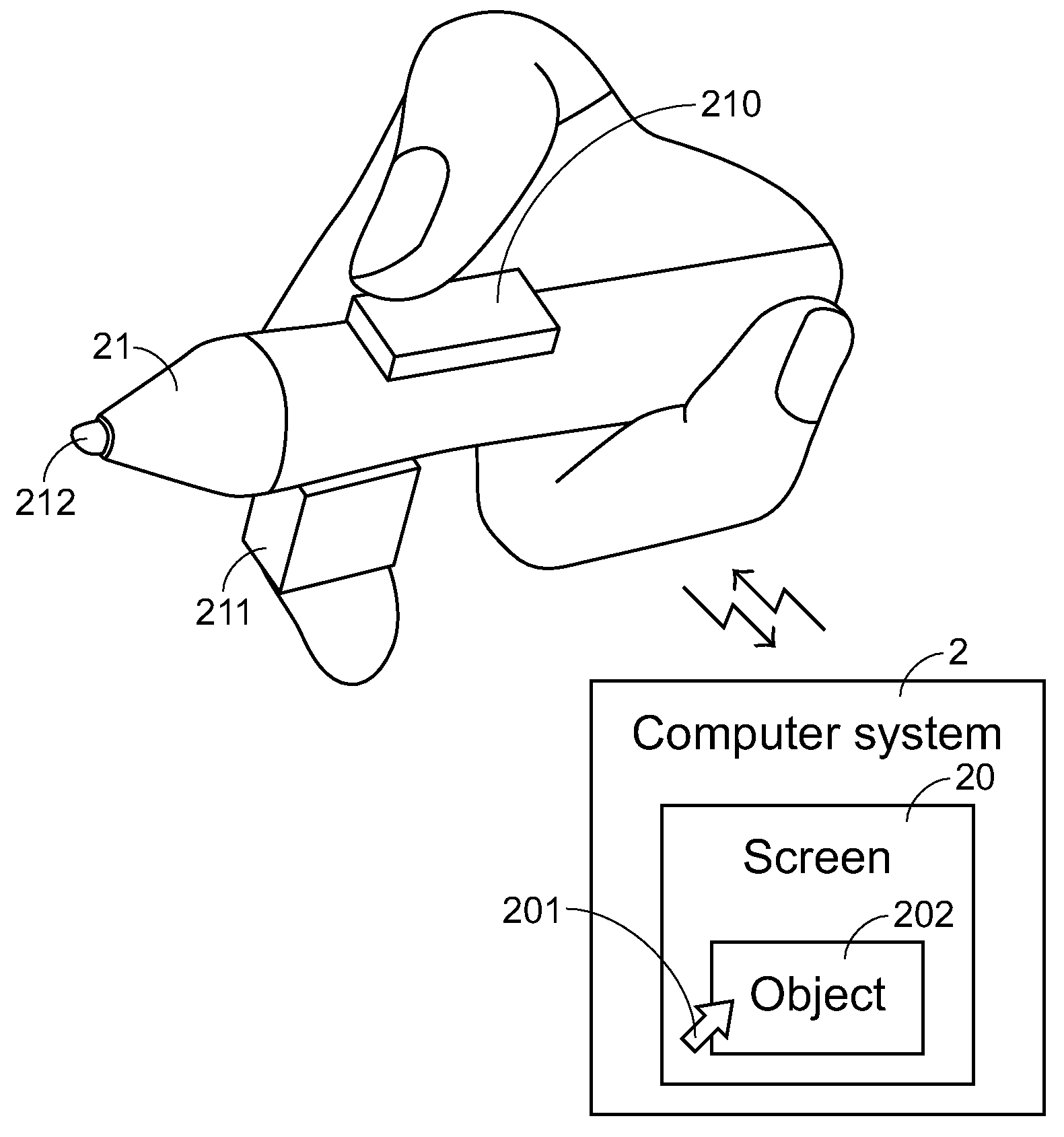
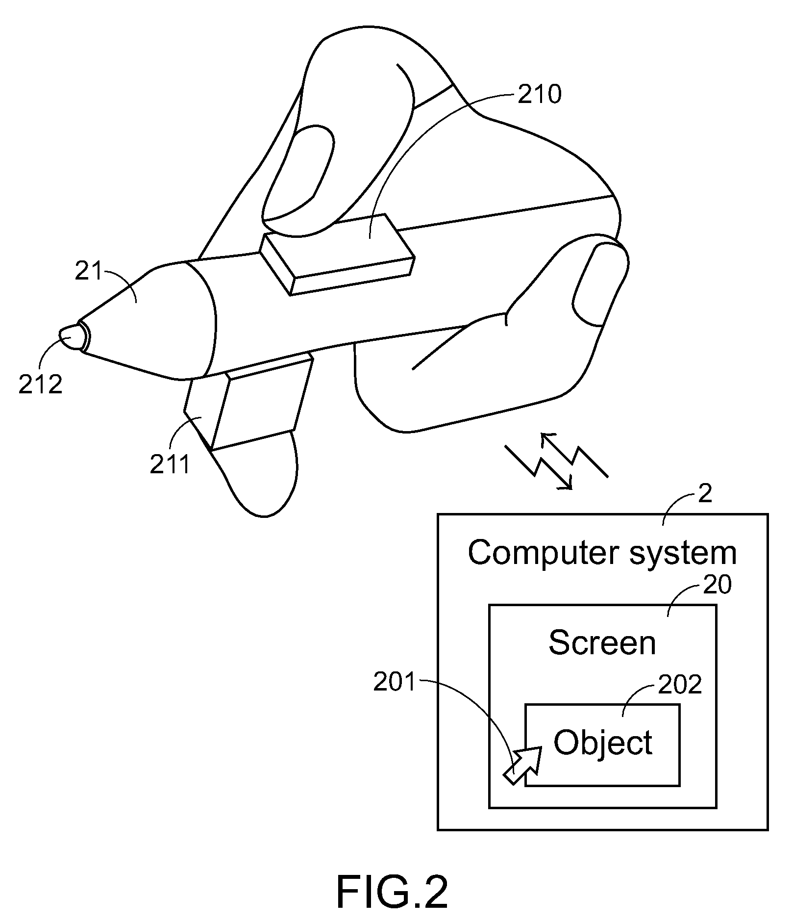
[0020]The present invention provides a cursor control device in order to obviate the drawbacks encountered from the prior art. FIG. 2 is a schematic outward view illustrating a cursor control device according to a preferred embodiment of the present invention. The cursor control device is applied to a computer system 2. The cursor control device is communicated with the computer system 2 in a wired or wireless transmission manner. By operating the cursor control device, a cursor 201 and an object 202 shown on a screen 20 are controllable. As shown in FIG. 2, the cursor control device principally comprises a pen-like body 21, a mo...


PUM


Abstract

A cursor control device includes a pen-like body, a motion-detecting element, a microcontroller and a button element. The motion-detecting element is disposed at a first side of the pen-like body for generating a coordinate change signal in response to a motion of a first finger of the user. The microcontroller is disposed within the pen-like body and communicated with the motion-detecting element and the computer system. According to the coordinate change signal, the microcontroller issues a cursor control signal to the computer system. The button element is disposed at a second side of the pen-like body and communicated with the microcontroller for triggering the microcontroller to generate an object locking control signal in response to a depressing action of a second finger of the user. The object pointed by the cursor is locked according to the object locking control signal and moved according to the cursor control signal.

Description

FIELD OF THE INVENTION[0001]The present invention relates to a cursor control device, and more particularly to a cursor control device for use with a computer system.BACKGROUND OF THE INVENTION[0002]Human-machine interface input devices are essential components of various electronic information products such as personal computers. In the early stage, the customarily used human-machine interface input devices include for example keyboards, trackballs, mice, touch pads, and so on. For helping the user well operate the computer system, the human-machine interface input devices are continuously developed in views of intuitive, easy-to-use and swift operations. Recently, a presenter is an exemplary human-machine interface input device complying with these requirements.[0003]FIG. 1 is a schematic functional block illustrating collective operations of a conventional presenter and a personal computer. According to a command inputted into the presenter 10 by a user, the presenter 10 issues a...

Claims


Application Information

Patent Timeline
Patent Type & Authority Applications(United States)
IPC IPC(8): G06F3/033G06F3/0354G06F3/038
CPCG06F3/03545G06F2203/0384G06F3/0383G06F3/03547
Inventor YEN, CHRISTOPHERWU, JIUN-SHINLEE, TZUNG-LINYU, CHEN-HSIANGKUO, MEI-JEN
Owner AVER INFORMATION INC
Features
  • R&D
  • Intellectual Property
  • Life Sciences
  • Materials
  • Tech Scout
  • Unparalleled Data Quality
  • Higher Quality Content
  • 60% Fewer Hallucinations
Learn More