
Apparatus for and method of controlling jetting of ink in inkjet printer

Inactive Publication Date: 2010-01-07
HEWLETT PACKARD DEV CO LP
View PDF5 Cites 19 Cited by
  • Summary
  • Abstract
  • Description
  • Claims
  • Application Information

AI Technical Summary

Benefits of technology

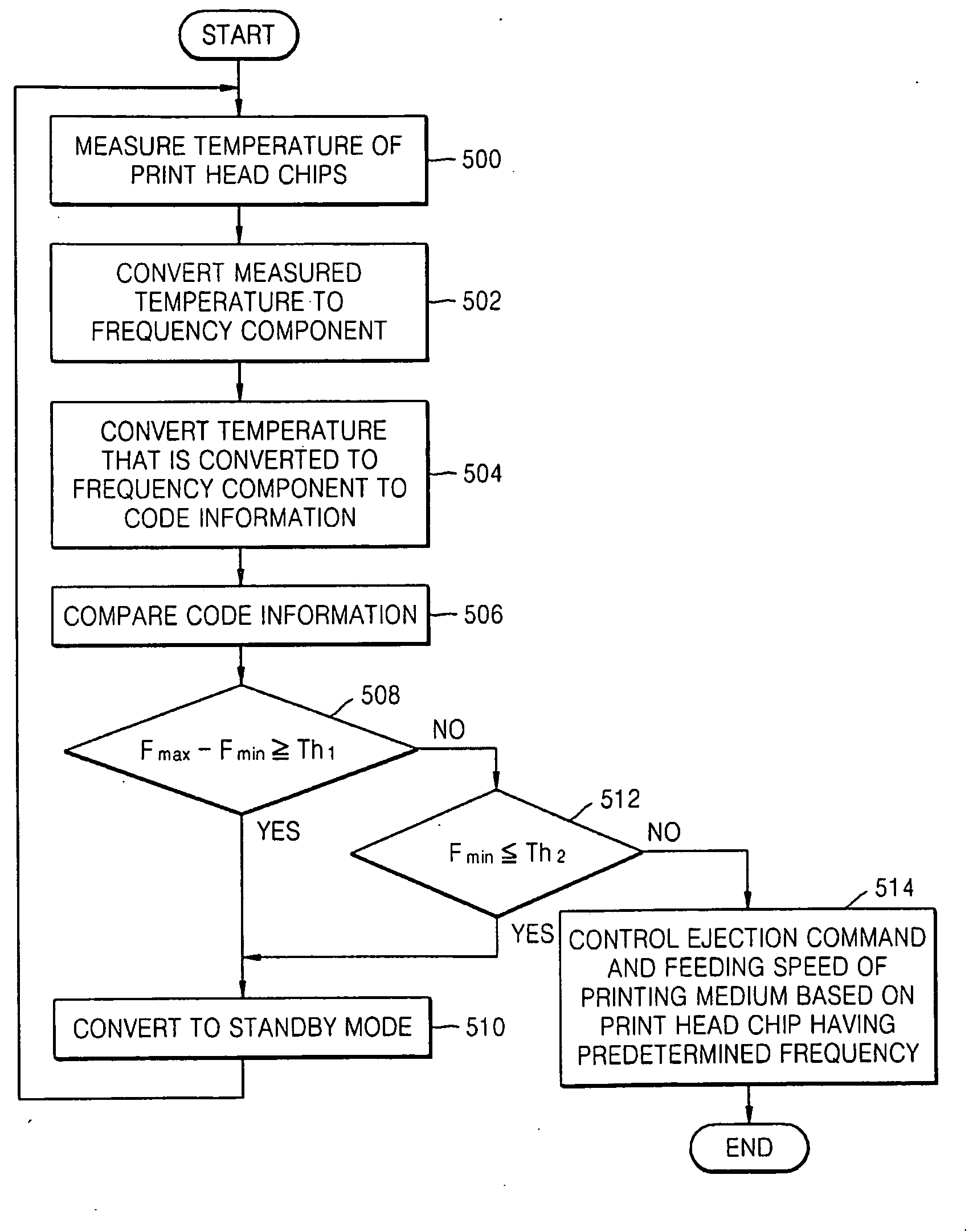
[0013]The controller may delay the timing of ink ejection when the temperature of the select one of the plurality of print head chips is higher than a predetermined temperature. The controller may advance the timing of ink ejection when the temperature of the select one of the plurality of print head chips is lower than the predetermined temperature.
[0015]The controller may decrease the feeding speed of the printing medium when the temperature of the select one of the plurality of print head chips is higher than a predetermined temperature. The controller may increase the feeding speed of the printing medium when the temperature of the select one of the plurality of print head chips is lower than the predetermined temperature.
[0022]The step of controlling the timing of ink ejection may comprise: delaying the timing of ink ejection when the temperature of the select one of the plurality of print head chips is higher than a predetermined temperature; and advancing the timing of ink ejection when the temperature of the select one of the plurality of print head chips is lower than the predetermined temperature.
[0024]The step of controlling the feeding speed of the printing medium may comprise: decreasing the feeding speed of the printing medium when the temperature of the select one of the plurality of print head chips is higher than a predetermined temperature; and increasing the feeding speed of the printing medium when the temperature of the select one of the plurality of print head chips is lower than the predetermined temperature.

Problems solved by technology

The temperature related viscosity change affects the drop volume of the ejected ink, and as a result, affects the quality of an image printed on a printing medium, such as, e.g., on a sheet of a paper.
When printouts are repeatedly outputted in a high speed / high resolution mode, the temperature of a head chip may gradually increase, and when the temperature exceeds certain level, a stable ink ejection cannot be expected, and it may thus become necessary to stop the printing operation for certain cooling time.
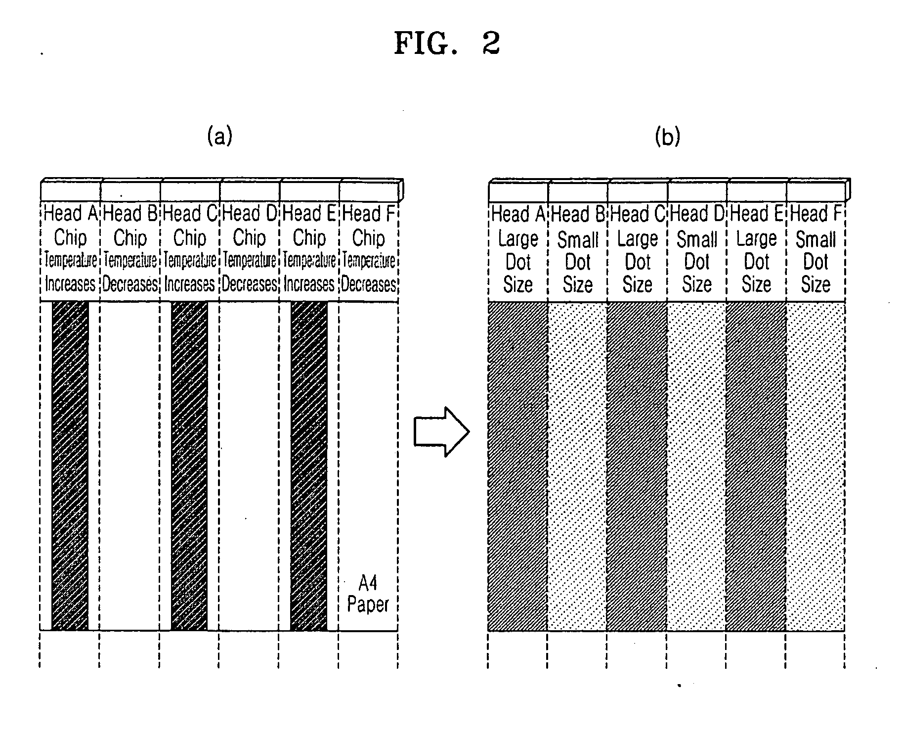
Moreover, when an array of head chips are employed, e.g., in a wide array printer, temperatures between adjacent head chips may differ, and such different temperatures may result in an inferior image quality.
The image quality may also deteriorate when the viscosity of ink increases, or when the temperature of the head chip becomes too low, and thereby, reducing the amount of the ink ejected.
When there is an optical density difference between adjacent head chips despite of the same input, lines appear in the image between the head chips, and thus, the resulting image pattern may appear distorted and different from the intended original image.

Method used


Image

  • Apparatus for and method of controlling jetting of ink in inkjet printer
  • Apparatus for and method of controlling jetting of ink in inkjet printer
  • Apparatus for and method of controlling jetting of ink in inkjet printer

Examples


Embodiment Construction

[0041]Reference will now be made in detail to embodiments of the present invention, examples of which are illustrated in the accompanying drawings, wherein like reference numerals refer to like elements. While the embodiments are described with detailed construction and elements to assist in a comprehensive understanding of the various applications and advantages of the embodiments, it should be apparent however that the embodiments can be carried out without those specifically detailed particulars. Also, well-known functions or constructions will not be described in detail so as to avoid obscuring the description with unnecessary detail.

[0042]FIG. 3 is a block diagram illustrating an apparatus for controlling jetting of ink of an inkjet printer according to an embodiment. The apparatus may include first through N-th print head chips 100 through 120, a counter 200, a comparator 300 and a controller 400.

[0043]Each of the first through N-th print head chips 100 through 120 may include...


PUM


Abstract

Provided are an apparatus and method of controlling jetting of ink of an inkjet printer. The apparatus includes at least one print head chip, which includes a temperature sensor for sensing the temperature of the print head chip and a voltage controlled oscillator (VCO) for converting the sensed temperature to a frequency component. The apparatus may also include a counter, which converts the frequency component to a code information using a reference frequency component, and a controller, which controls the ink jetting operation of the at least one print head chip based on the code information and / or the frequency component.

Description

CROSS-REFERENCE TO RELATED PATENT APPLICATION[0001]This application claims the benefit of Korean Patent Application No. 10-2008-0065137, filed on Jul. 4, 2008, in the Korean Intellectual Property Office, the disclosure of which is incorporated herein in its entirety by reference.TECHNICAL FIELD[0002]The present general inventive concept relates to an image forming apparatus, and more particularly, to apparatus for and method of controlling a plurality of print head chips so as to reduce the effect of temperature variance.BACKGROUND OF RELATED ART[0003]In conventional inkjet printers utilizing jetting of liquid ink, proper temperature control may be required in order to maintain a uniform printing because the viscosity of the liquid ink in the inkjet head chip changes according to the ambient and / or head chip temperatures. The temperature related viscosity change affects the drop volume of the ejected ink, and as a result, affects the quality of an image printed on a printing medium,...

Claims


Application Information

Patent Timeline
IPC IPC(8): B41J29/38
CPCB41J2/04541B41J2/0458B41J2/04563B41J2/0455B41J2/04586B41J2/14072B41J2/14427G01K1/026
Inventor JEONG, YONG-WONCHOI, HYUNGYOON, YUNG-SEOPLEE, MOON-CHULSHIM, DONG-SHIK
Owner HEWLETT PACKARD DEV CO LP
Learn More