Imaging auto shutter roi

a technology of auto shutter and image processing, applied in the field of imaging system using auto shutter, can solve the problems of wasteful further image processing of the entire detector area

Active Publication Date: 2010-01-07
VAREX IMAGING CORP
View PDF4 Cites 18 Cited by
  • Summary
  • Abstract
  • Description
  • Claims
  • Application Information

AI Technical Summary

Benefits of technology

[0027]In yet another embodiment, the system further includes setting values of the digital ima

Problems solved by technology

Further image processing of the entire detector area can be wasteful,

Method used


Image

  • Imaging auto shutter roi
  • Imaging auto shutter roi
  • Imaging auto shutter roi

Examples


Embodiment Construction

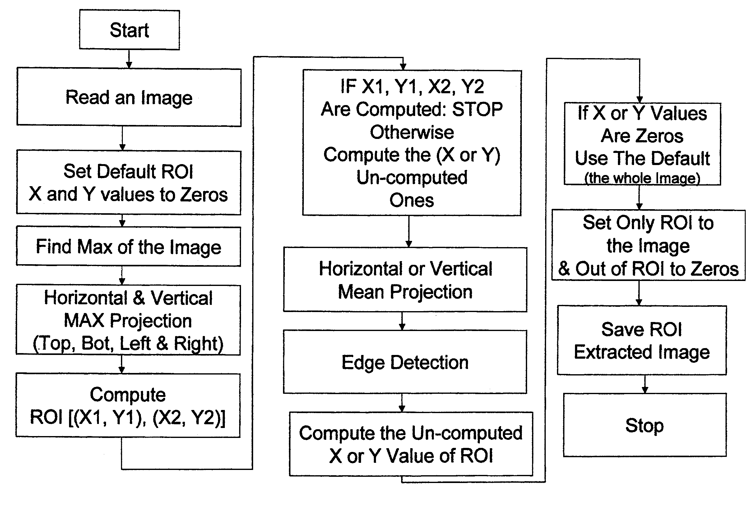
[0042]DEFINITIONS: A Mean projection of an image is considered herein to be a subset of the larger set of mathematical Radon transforms. By standard definition, Radon transforms, as shown in FIG. 9 can be performed on or off-axis with respect to a two dimensional Cartesian coordinate system. In general, a Radon transform is the integral of an N-dimensional function over a hyperplane. For a 2D function, the Radon transform is the integral of the function over a line. In image processing, a Radon transform is the projection of image intensity along a radial line oriented at a specific angle. For example, horizontal and vertical projections are commonly used for Radon transforms in image processing.

[0043]“Saving” or recording data such as intermediate data, calculations, or the results of an auto shutter ROI operation to memory, such as for example, recording ROI and image information is understood to mean and defined herein as “writing” output data to a storage element or device. For ...


PUM


Abstract

A method to identify a Region Of Interest (ROI) within an image includes the steps of: reading a digital image; finding predetermined brightness values; analyzing lines near a plurality of outer edges of the digital image; identifying an entire area of the digital image as the ROI if the found brightness values are also found in lines near the plurality of outer edges of the digital image; computing Radon transforms to generate one dimensional (1D) projections of the digital image if the found brightness values are not found in the lines; detecting a set of edges within the 1D projections; selecting edges from the set of edges; validating the selected edges to identify a set of validated edges; computing the ROI from the set of validated edges of the 1D projections; and saving the computed ROI to memory. A system to perform the method is also described.

Description

FIELD OF THE INVENTION [0001]This invention relates generally to an imaging system using autoshutter and more particularly to a method for finding a region of interest in a digital image.BACKGROUND OF THE INVENTION [0002]In medical imaging, such as digital radiography, one significant goal is minimize patient exposure to x-rays. As such, medical imaging X-ray light source typically includes movable (adjustable) “blades” that limit an area of exposure to the general vicinity of the section of human anatomy of interest, the “Region Of Interest” (ROI). For example, a relatively small exposure area might be used to image a human hand. There can be four blades (e.g. right, left, top, and bottom) that can range from fully open (maximum exposure area), to partially closed, causing a relatively small rectangular exposure area. Imaging equipment generally provides a sensor or detector that records the maximum possible exposure area and generates a digital image. The digital image contains ex...

Claims


Application Information

Patent Timeline
IPC IPC(8): G06K9/00G06V10/25
CPCG06K2209/05G06K9/3233G06V10/25G06V2201/03
Inventor KALAYEH, HOOSHMAND M.
Owner VAREX IMAGING CORP
Why Eureka
Try Eureka