Appliance with animation framework

an animation framework and application technology, applied in the field of appliances, can solve the problems of not being able to adapt to the communication between additional external/internal components, inability to modify, and inability to couple additional external components or additional internal components to the appliance to expand the capability or function of the applian

Active Publication Date: 2010-01-07
WHIRLPOOL CORP
View PDF14 Cites 49 Cited by
  • Summary
  • Abstract
  • Description
  • Claims
  • Application Information

AI Technical Summary

Problems solved by technology

The hard-wired connectors form a closed system or network that is difficult or not possible to modify.
For example, because the closed network relies on hard-coded or hard-wired network solutions, it is not practical to couple additional external components or additional internal components to the appliance to expand the capability or function of the appliance.
The closed network cannot easily be adapted for communication with the additional external / internal components and therefore limits the potential of the appliance.
However, scheduling appointments with service personnel can be inconvenient, and accessing the interior of the appliance can require the use of specialized tools and can potentially damage the appliance in the process.
In addition, due to the limited potential of the internal components, the user of the appliance is unable to thoroughly personalize the operation of the appliance in order to tailor the appliance to his or her particular needs.

Method used


Image

  • Appliance with animation framework
  • Appliance with animation framework
  • Appliance with animation framework

Examples


first embodiment

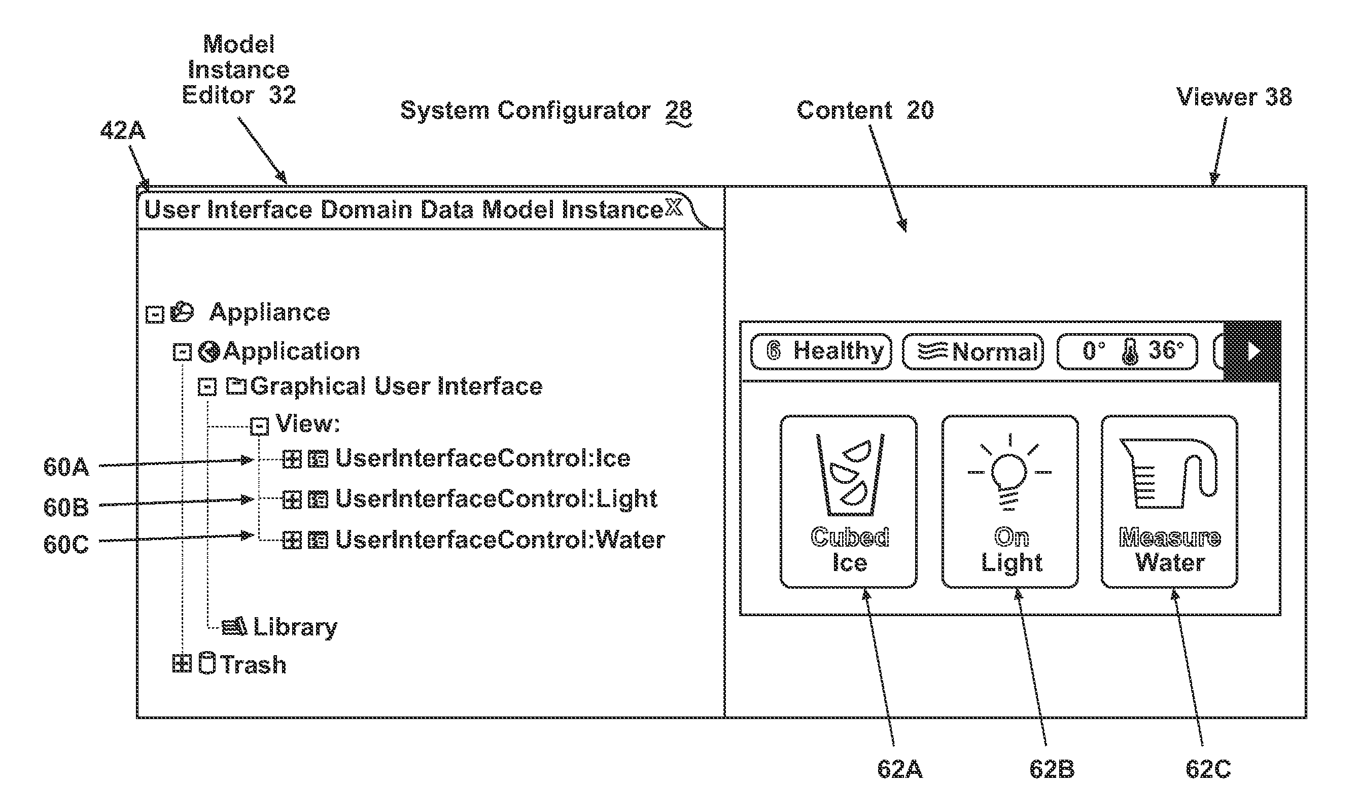
[0134]Looking now to FIGS. 30-42, in a first embodiment, a hierarchy of objects starts with a single root object that we can call “root.” The root object has 0 to n children and the children may be of different types (i.e., type 1 and type 2). In turn, the 0 to n children may also have children. Therefore, an object A that is a child of root and has children of B and C is considered to be both a child and a parent and can be referred to either as a child or a parent depending on the context. Except for the root, all objects in a hierarchy are a child and those with children are also parents. The root is a parent unless it has no children.

[0135]The first embodiment is a simple example of an implementation of a hierarchy wherein the parent child relationships are direct relationships. In a direct parent child relationship, the parent includes an identifier identifying each of its children. Therefore, the parent cannot be decoupled from its children because it comprises the identifiers...

second embodiment

[0136]A second embodiment exemplifies an indirect parent child relationship wherein neither the parents nor the children include identifiers of the other. Instead, a holder object contains the identifiers of both. For example, object Q is a holder and contains an identifier of object A, object B, and object C, wherein object A is of type 1, object B is of type 2 and object C is of type 3. Objects A, B, and C do not have access to the identifiers of one another. The primary responsibility of object Q is to contain identifiers for objects A, B, and C thereby establishing that there is some type of relationship between objects A, B, and C. There are a number of ways that the nature of the relationship between A, B, and C can be ascertained. In a first example, object Q has access to information defining the possible relationships between objects of type 1, 2, and 3. In this example the information would define a first relationship definition between objects of type 1 and type 2 as bein...

third embodiment

[0137]A third embodiment exemplifies an alternate approach for creating an indirect parent child relationship wherein neither the parents nor the children include identifiers of the other. In this embodiment, multiple holders are used to create a holder hierarchy. For example, object Q is a holder and contains an identifier for object A. Object Q also contains an identifier for a second holder object X. Object X contains an identifier for object B. Holder object Q is a parent holder with respect to holder object X because holder object Q contains the identifier to holder object X. Therefore the relationship between object A and object B be can be inferred as a parent child relationship when observed from the perspective of holder object Q and holder object X because holder object Q are in a direct parent child relationship. In this case, object A and object B are in an indirect parent-child relationship.

[0138]A forking element includes a hierarchy having a first parent object with a...


PUM


Abstract

An appliance includes one or more control boards having control software to control a cycle of operation, access to memory, a graphical user interface in communication with the control boards for allowing a user to observe and interact with the appliance regarding the cycle of operation, and a software framework in communication with the graphical user interface and the memory access. The software framework has animation definitions and access to builder content containing instance information with which it can create at least one instance of a user interface control and can associate one or more animation definitions with memory information associated with at least two locations in the memory. With this structure, the software framework dynamically renders animation in the graphical user interface at runtime using the animation definitions, and the rendering of the graphical user interface is dynamically affected by association of the animation definitions and the memory information.

Description

CROSS REFERENCE TO RELATED APPLICATIONS[0001]This application is a continuation of PCT / US2009 / 046186 filed Jun. 3, 2009, which claims priority from U.S. Application Ser. No. 61 / 058,440 filed Jun. 3, 2008.FIELD OF THE INVENTION[0002]The invention relates to the operation of appliances and more particularly, to the rendering of animations on a graphical user interface in an appliance.DESCRIPTION OF THE RELATED ART[0003]Household appliances typically comprise one or more components responsible for the electromechanical operations of the appliance. For example, an oven can include an appliance management component having a printed circuit board (PCB) with memory, as well as a user-interface component, such as a control panel or keypad, for a user to issue commands to the oven. As another example, a washing machine can include an appliance management component, a user-interface component, and a motor control component that controls a motor of the washing machine.[0004]Typically, discrete...

Claims


Application Information

Patent Timeline
Patent Type & Authority Applications(United States)
IPC IPC(8): G06F3/048G05B15/00
CPCG06F8/10G06F8/36G06F8/38Y10S715/965H04L12/2814H04L2012/285H04L67/125G06F11/263
Inventor EBROM, MATTHEW P.GLOTZBACH, MARK E.MCCOY, RICHARD A.RADFORD, BRIAN N.
Owner WHIRLPOOL CORP
Why Eureka
Try Eureka