Coin lock

Inactive Publication Date: 2010-01-14
ASSA
View PDF3 Cites 2 Cited by
  • Summary
  • Abstract
  • Description
  • Claims
  • Application Information

AI Technical Summary

Benefits of technology

[0007]Another aim is to provide such a coin lock in which

Problems solved by technology

Furthermore, it is not possible to alter the maximum permissible coin diameter of an existing lock, unless the lock is opened, the previous coin limiting arrangement is removed, a new coin limiting arran

Method used


Image

  • Coin lock
  • Coin lock
  • Coin lock

Examples


Example

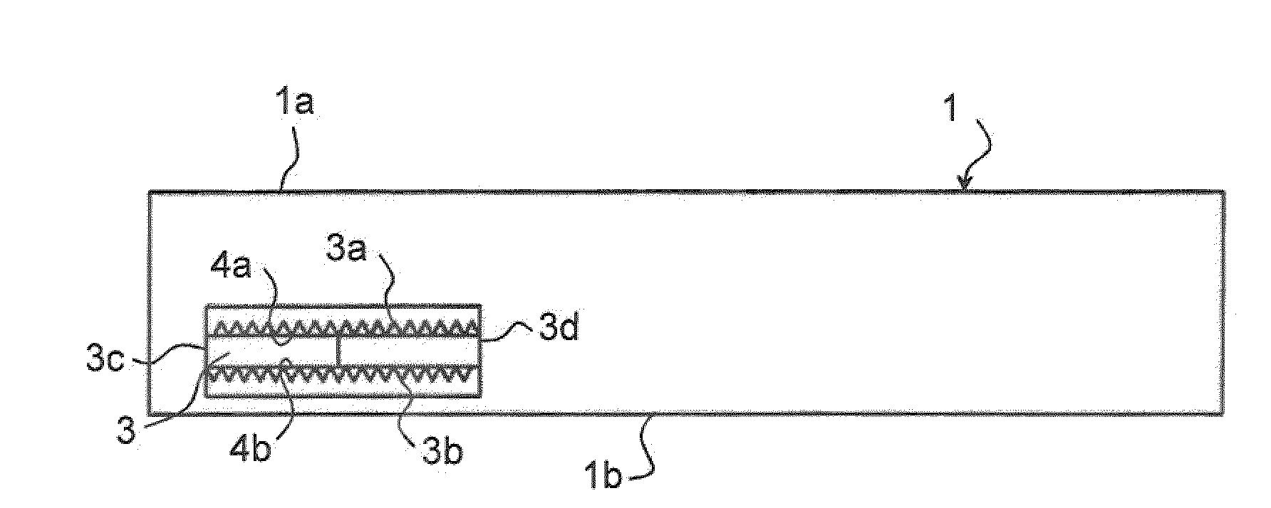
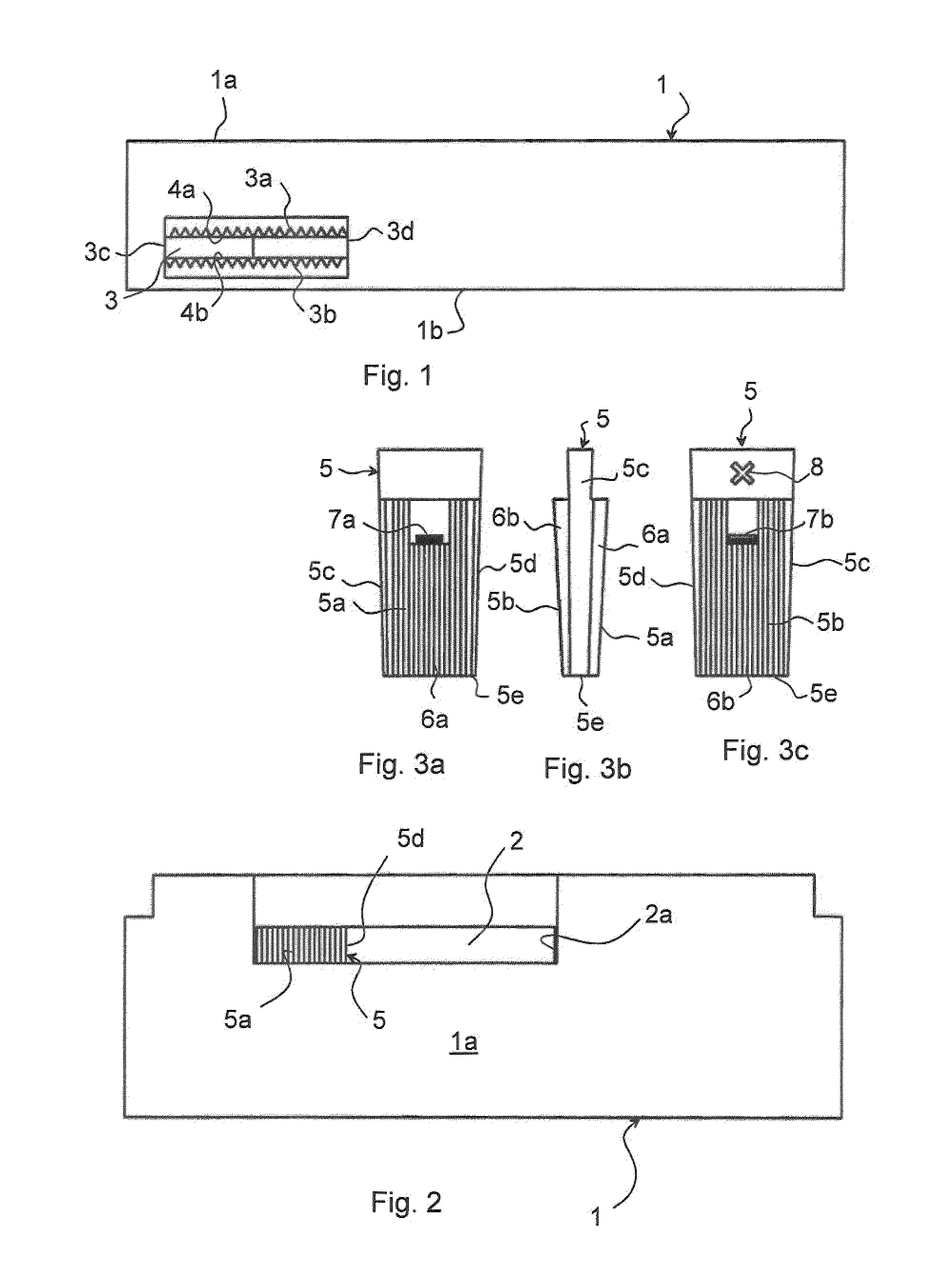
[0026]FIGS. 1 and 2 show a coin opening part configured as a module unit for a coin lock according to a first embodiment of the invention. The coin opening part 1 can be easily attached to different lock housings for coin locks to be provided with a coin limiting arrangement. The coin opening part 1 has, on its top side 1a, the mouth of a coin opening. The coin opening is defined by a coin channel 2 which extends perpendicularly downward from the top side 1a of the opening part 1 and through the coin opening part 1 to its bottom side 1b. The coin opening channel 2 and thus the coin opening have an oblong rectangular cross section. The length of the cross section is equal to or slightly larger than the diameter of the largest coin that can be introduced into the coin lock through the coin channel 2. The width of the cross section is sufficiently large to allow insertion of the thickest coin that can be introduced through the coin channel. In use, the coin opening part is secured to a...


PUM


Abstract

Coin lock comprising a lock housing, a coin opening part (1) with a coin opening having an oblong cross section perpendicular to the direction of inserting the coin, for introducing a coin into the lock housing, and a coin limiting arrangement which is designed to prevent a coin with a diameter bigger than a defined maximum diameter from being introduced into the lock housing through the coin opening. The coin limiting arrangement comprises a blocking element (5, 50, 51) which can be inserted from the outside into the coin opening and which comprises first engaging units which are designed, in engagement with second engaging units arranged at the coin opening part, to enable a detachable fixation of the blocking element in the coin opening at various positions along the lengthways direction of the coin opening's cross section.

Description

BACKGROUND AND FIELD OF THE INVENTION[0001]The invention relates to a coin lock and more specifically to a coin lock of the kind indicated in the preamble of claim 1.[0002]Such coin locks can be used, for example, in cabinets and storage boxes at public places such as sports halls, public swimming baths, train stations, airports and the like.[0003]The coin locks can operate on the pawn principle, when the coin inserted is returned after use, or on the pay principle, when the coin is not returned.[0004]For such coin locks it may be desirable to limit the size of the coin opening so that only coins of a certain maximum diameter can be introduced into the lock housing.PRIOR ART[0005]EP 0 945 836 A describes a coin lock which can be manoeuvred after a coin has been inserted through a coin opening in the lock. The coin lock can be provided with a coin limiting arrangement which is attached directly in front of the coin opening during assembly of the coin lock. The coin limiting arrangeme...

Claims


Application Information

Patent Timeline
IPC IPC(8): G07F5/02
CPCG07F1/02
Inventor HAGGSTROM, AKE
Owner ASSA
Why Eureka
Try Eureka