
Multi-channel video mixer for applying visual effects to video signals

Active Publication Date: 2007-06-26
YAMAHA CORP
View PDF4 Cites 7 Cited by
  • Summary
  • Abstract
  • Description
  • Claims
  • Application Information

AI Technical Summary

Benefits of technology

[0014]The present invention has been made to solve the above-mentioned problem, and it is an object thereof to provide a visual effect applying apparatus and a program for visual effect application, which make it easy to vary with time a visual effect applied with operators.

Problems solved by technology

However, since simultaneous operation of multiple operators is an error-prone operation, some skill is required to manipulate the operators.
Further, since the operators are operated manually, it is difficult to repeat the same operation of the operators.
Especially when video signals inputted in real time need to be outputted in real time, quick manipulation of the controls is required and this makes it very difficult to make a sudden change in visual effect.
In other words, it does not allow for recording and reproducing a gradual change in visual effect in a period of transition during which the visual effect gradually varies.

Method used


Image

  • Multi-channel video mixer for applying visual effects to video signals
  • Multi-channel video mixer for applying visual effects to video signals
  • Multi-channel video mixer for applying visual effects to video signals

Examples


Embodiment Construction

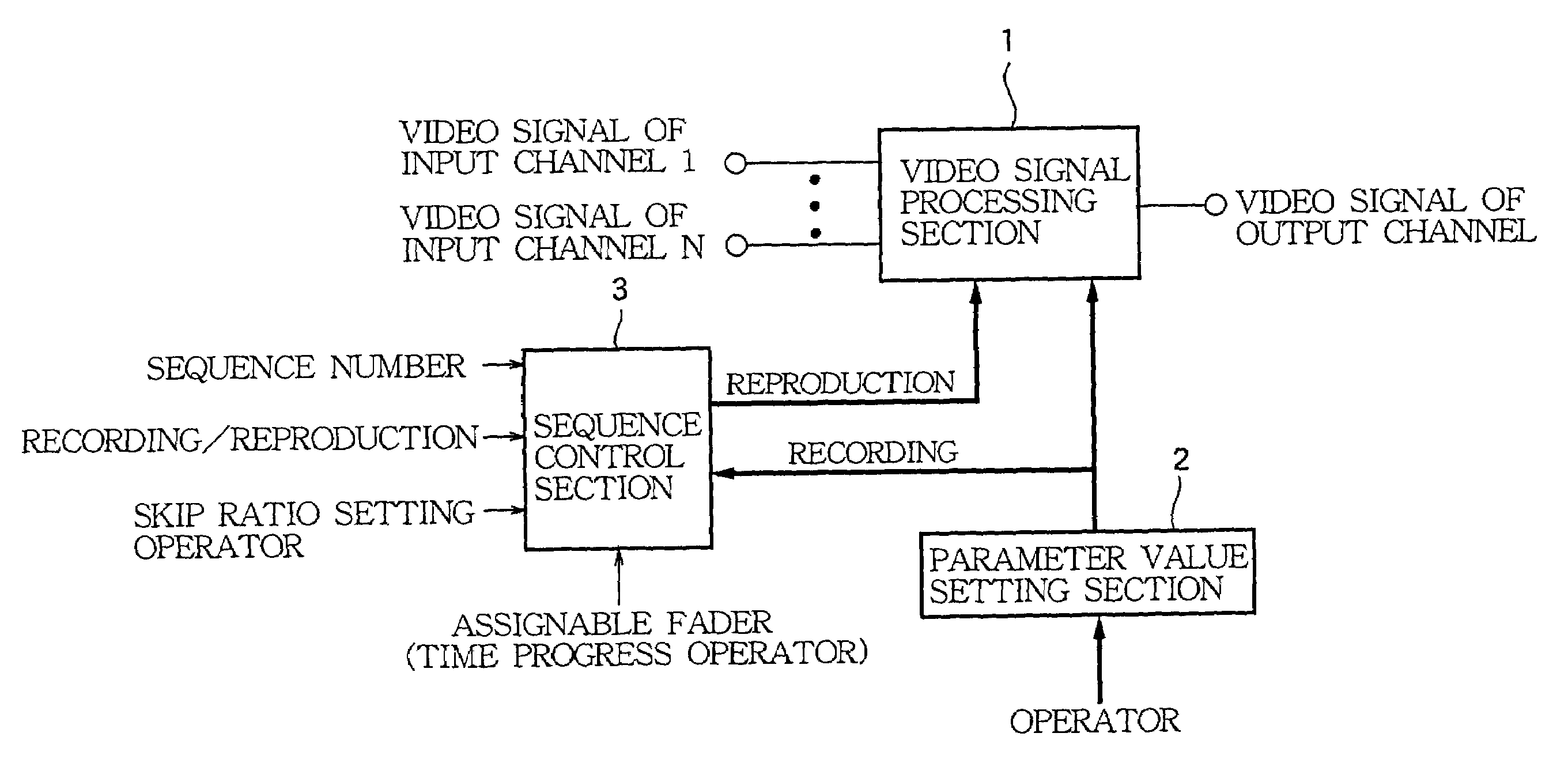
[0041]FIG. 1 is a block diagram for explaining an embodiment in which the present invention is applied to a video mixer apparatus.

[0042]The video mixer apparatus prestores as sequence data setting states of parameters varied by a human operator who adjusts operators as time progresses. The video mixer apparatus can read the recorded sequence data at any later time to reproduce the operating procedure for control of the operators. This makes it easy to control a complicated visual effect varying with time.

[0043]As shown, reference numeral 1 designates a video signal processing section, reference numeral 2 is a parameter value setting section, and reference numeral 3 is a sequence control section. Unlike conventional video mixer apparatuses, the video mixer apparatus of the present invention has the sequence control section 3 to expand its visual effect features.

[0044]The video signal processing section 1 takes in video signals of multiple input channels, and processes each of the vid...


PUM


Abstract

A digital video mixer apparatus is designed for inputting a video signal representative of a picture from a plurality of input channels, then processing the video signal to apply a visual effect to the picture, and outputting the processed video signal to an output channel. In the apparatus, a parameter value setting section includes a plurality of operators manually operable to set a plurality of parameter values used for applying a desired visual effect to the picture. A sequence control section sequentially feeds the parameter values in accordance with time progress of processing the video signal in order to vary with time the visual effect applied to the picture. A video signal processing section processes the video signal inputted from at least one of the input channels according to either of the parameter values set by the operators or the parameter values fed from the sequence control section.

Description

BACKGROUND OF THE INVENTION[0001]1. Technical Field of the Invention[0002]The present invention relates to an apparatus for applying visual effects to video signals, and a program for visual effect application. In particular, the present invention pertains to a video mixer apparatus for mixing video signals of multiple channels while applying a visual effect to each of the video signals to output a mixed video signal.[0003]2. Prior Art[0004]A video mixer apparatus mixes video signals of multiple input channels specified by a human operator of the video mixer apparatus to output a mixed video signal in real time. Upon this operation, the video mixer apparatus selects input channels, sets a mixing ratio among video signals of the multiple input channels, and sets a visual effect to be applied to each of the video signals of the respective input channels.[0005]At the time of switching between input channels, the human operator may want to gradually change scenes from the preceding pict...

Claims


Application Information

Patent Timeline
IPC IPC(8): H04N9/74H04N5/262H04N9/76
CPCH04N9/74H04N9/76
Inventor IWASE, HIROYUKI
Owner YAMAHA CORP
Learn More