Imaging device and image acquiring method

Inactive Publication Date: 2008-01-24
SEIKO EPSON CORP
View PDF9 Cites 13 Cited by
  • Summary
  • Abstract
  • Description
  • Claims
  • Application Information

AI Technical Summary

Benefits of technology

[0008] An advantage of some aspects of the invention is that it provides a photography technology with which the depth of field can be easily varied.

Problems solved by technology

However, a user who is not accustomed to using cameras may not be familiar with camera functions for adjusting the aperture so as to vary the depth of field.
In addition, it is very difficult for such a user who is not accustomed to using cameras to appropriately set the depth of field so as to freely adjust the degree of a blur mode of an image.

Method used


Image

  • Imaging device and image acquiring method
  • Imaging device and image acquiring method
  • Imaging device and image acquiring method

Examples


first embodiment

A. First Embodiment

Configuration of Device

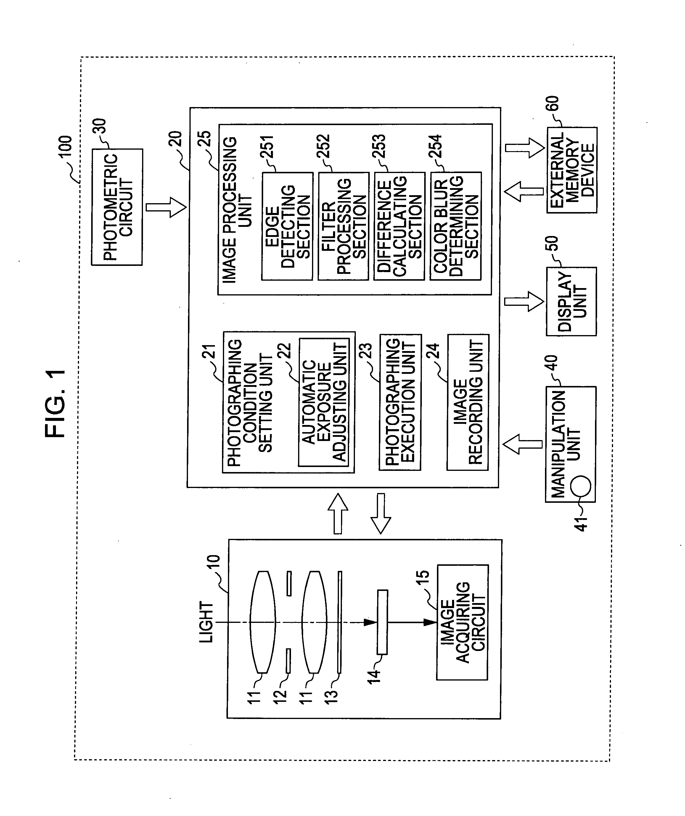
[0037] Next, an embodiment of an invention will be described. FIG. 1 is a schematic view illustrating a digital camera as an imaging device according to a first embodiment.

[0038] A digital camera 100 includes a photographing unit 10, a control unit 20, a photometric circuit 30 which measures the brightness of a subject, a manipulation unit 40, a display unit 50 such as a liquid crystal, and an external memory device 60.

[0039] The photographing unit 10 actually photographs and outputs image data generated after photographing to a control unit 20. The photographing unit 10 includes a lens 11, a diaphragm mechanism 12, a shutter 13, an image sensor 14, and an image acquiring circuit 15. The lens 11 collects light from the subject to a light-receiving surface of the image sensor 14 so as to form an image of the subject on the light-receiving surface of the image sensor 14. The diaphragm mechanism 12 is a mechanism which adjusts the amount of...

second embodiment

B. Second Embodiment

[0081] In the first embodiment, the color blur determining process is performed in the digital camera 100, but it is not limited to the digital camera. For example, the image processing unit 25 performing the color blur determining process may be mounted to a personal computer or to a print device such as an inkjet printer. With reference to FIGS. 8 to 10, an embodiment mounting the image processing unit 25 which performs the color blur determining process to a personal computer will be explained as a second embodiment. FIG. 8 is a schematic flowchart of the second embodiment. FIG. 9 is a flowchart illustrating an operation of the digital camera according to the second embodiment. FIG. 10 is a flow chart illustrating an operation of a personal computer according to the second embodiment.

System Configuration

[0082] A system of the second embodiment includes a digital camera 100b and a personal computer 200. In the second embodiment, the control unit 20 of the di...

first modified example

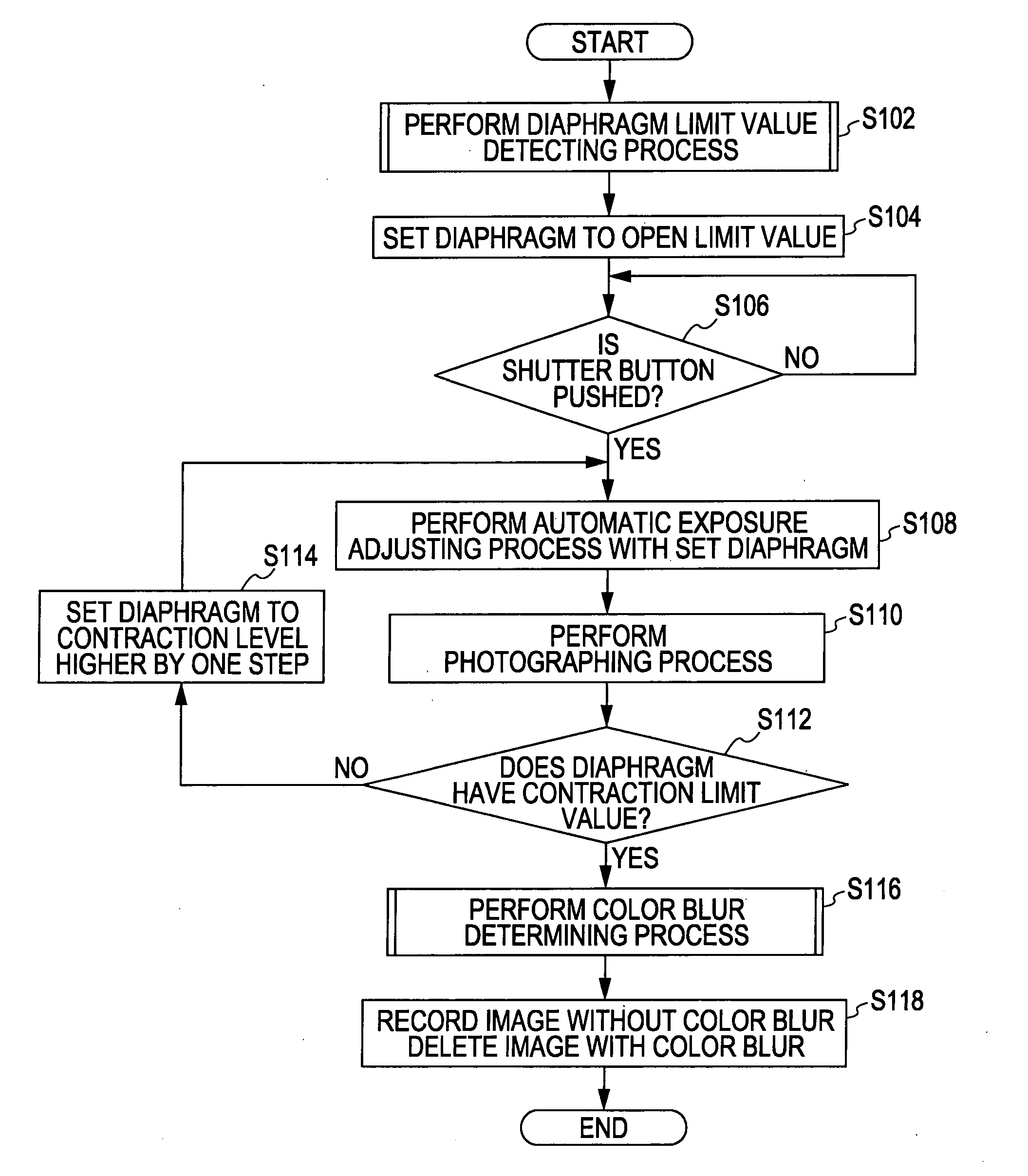
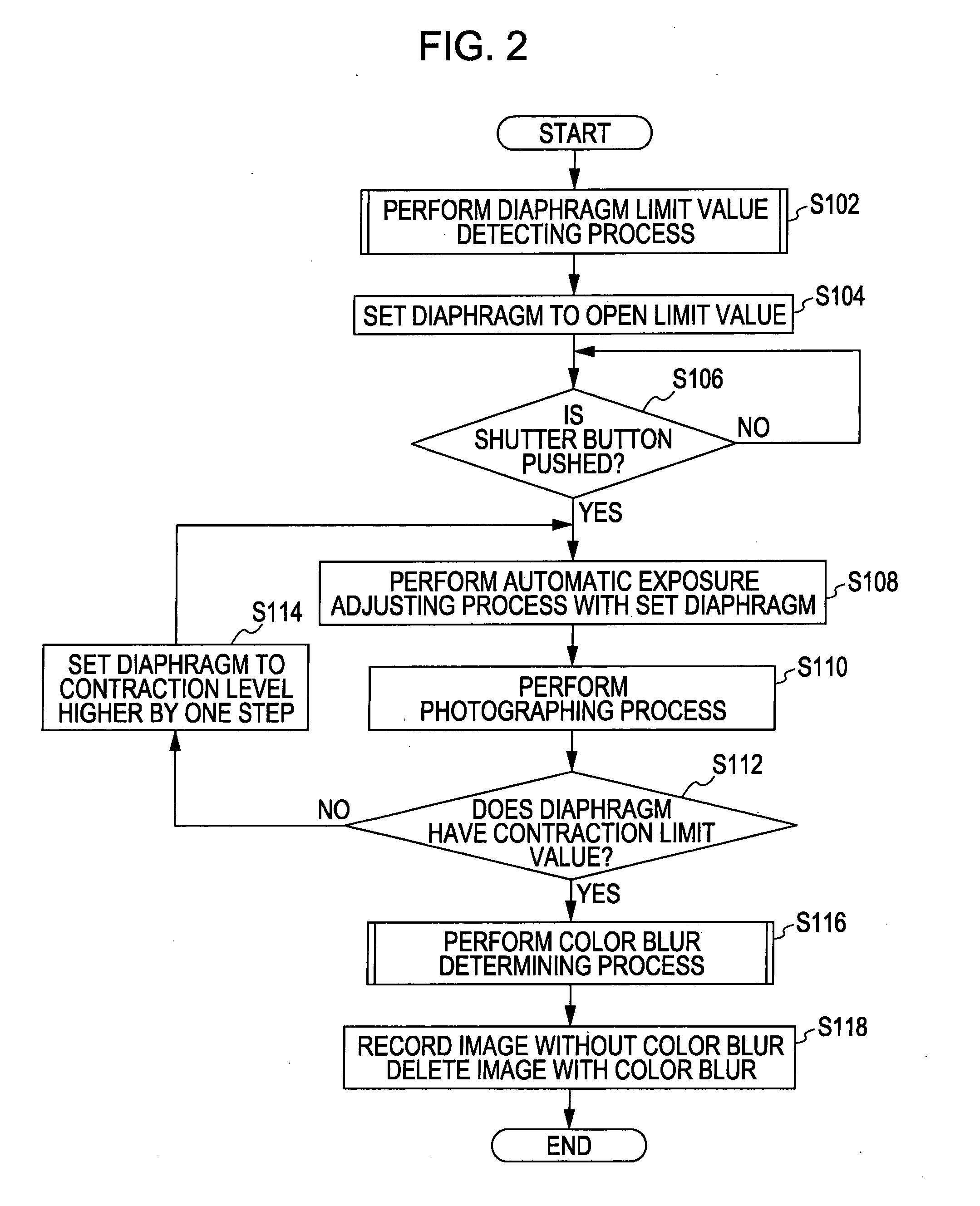
[0091] With reference to FIG. 11, an operation of the digital camera 100 according to a first modified example will be described. FIG. 11 is a flow chart illustrating the operation of the digital camera 100 according to the modified example. Since steps s402 to s406 of the modified example are similar to steps s102 to s106 (FIG. 2) of the first example, the descriptions thereof will be omitted. In step s406, when the user pushes the shutter button 41 so as to input the photographing instruction (step s106: YES), the automatic exposure adjusting unit 22 performs the automatic exposure adjusting process by using the aperture which is set to the open limit state (step s408). Accordingly, ISO sensitivity and the shutter speed are determined so that the aperture is set to the open limit. When the automatic exposure adjusting ends, the photographing execution unit 23 performs the photographing process to the photographing unit 10 in accordance with the determined photographing modes (aper...


PUM


Abstract

Provided is an imaging device including a photographing instruction input unit which inputs a photographing instruction, a mode setting unit which sets a plurality of photographing modes including substantially the same amount of exposure and different aperture and a photographing unit which performs continuously a photographing process using the plurality of photographing modes in accordance with the photographing instruction.

Description

BACKGROUND [0001] 1. Technical Field [0002] The present invention relates to an imaging device and a method of acquiring a plurality of images. [0003] 2. Related Art [0004] A camera having a photographing function of exposure bracketing having slightly differing exposure times so as to take a plurality of photographs is widely known (e.g., JP-A-5-303130). In addition, a camera having a photographing function of focus bracketing which varies a focusing state by degrees and a photographing function of flash bracketing which varies the strength of a flash by degrees is known. In addition, other than the photographing function of exposure bracketing, a digital camera having a photographing function of white balance bracketing which varies white balance (color temperature) and a photographing function of sensitivity bracketing which varies the sensitivity of an imaging element is known (e.g., JP-A-7-318785). [0005] Herein, in the case of a silver salt camera or a digital camera, photogra...

Claims


Application Information

Patent Timeline
IPC IPC(8): G03B17/00G03B7/00G03B7/093G03B7/095G06T3/00G06T5/00H04N1/48H04N1/60H04N5/235H04N9/04H04N101/00
CPCG03B7/08H04N23/6845
Inventor KASAHARA, HIROKAZUTEZUKA, MUTSUTOTANAKA, TAKASHIGEFUKASAWA, KENJINAGAISHI, MICHIHIRO
Owner SEIKO EPSON CORP
Why Eureka
Try Eureka