Aerodynamic body and carrier wing comprising an aerodynamic body, actuating drive control module, computer, computer program and method for influencing post-turbulences

Active Publication Date: 2010-01-14
TECH UNIV MUNCHEN +1
View PDF13 Cites 46 Cited by
  • Summary
  • Abstract
  • Description
  • Claims
  • Application Information

AI Technical Summary

Benefits of technology

[0042]Flow flaps according to the invention make it possible to influence the wake eddy system without intervening in the functionality of already present control surfaces, such as ailerons or spoilers. Giving the flaps a multi-part configurat

Problems solved by technology

This can lead to serious consequences, especially for an aircraft smaller than the aircraft flying ahead of it.
These are manifested in an elevated structural dynamic load, ultimately resulting in a loss of stable attitude, for example if the planned rolling moment is no longer sufficient to compensate for the rolling moment induced by the eddy

Method used


Image

  • Aerodynamic body and carrier wing comprising an aerodynamic body, actuating drive control module, computer, computer program and method for influencing post-turbulences
  • Aerodynamic body and carrier wing comprising an aerodynamic body, actuating drive control module, computer, computer program and method for influencing post-turbulences
  • Aerodynamic body and carrier wing comprising an aerodynamic body, actuating drive control module, computer, computer program and method for influencing post-turbulences

Examples


Embodiment Construction

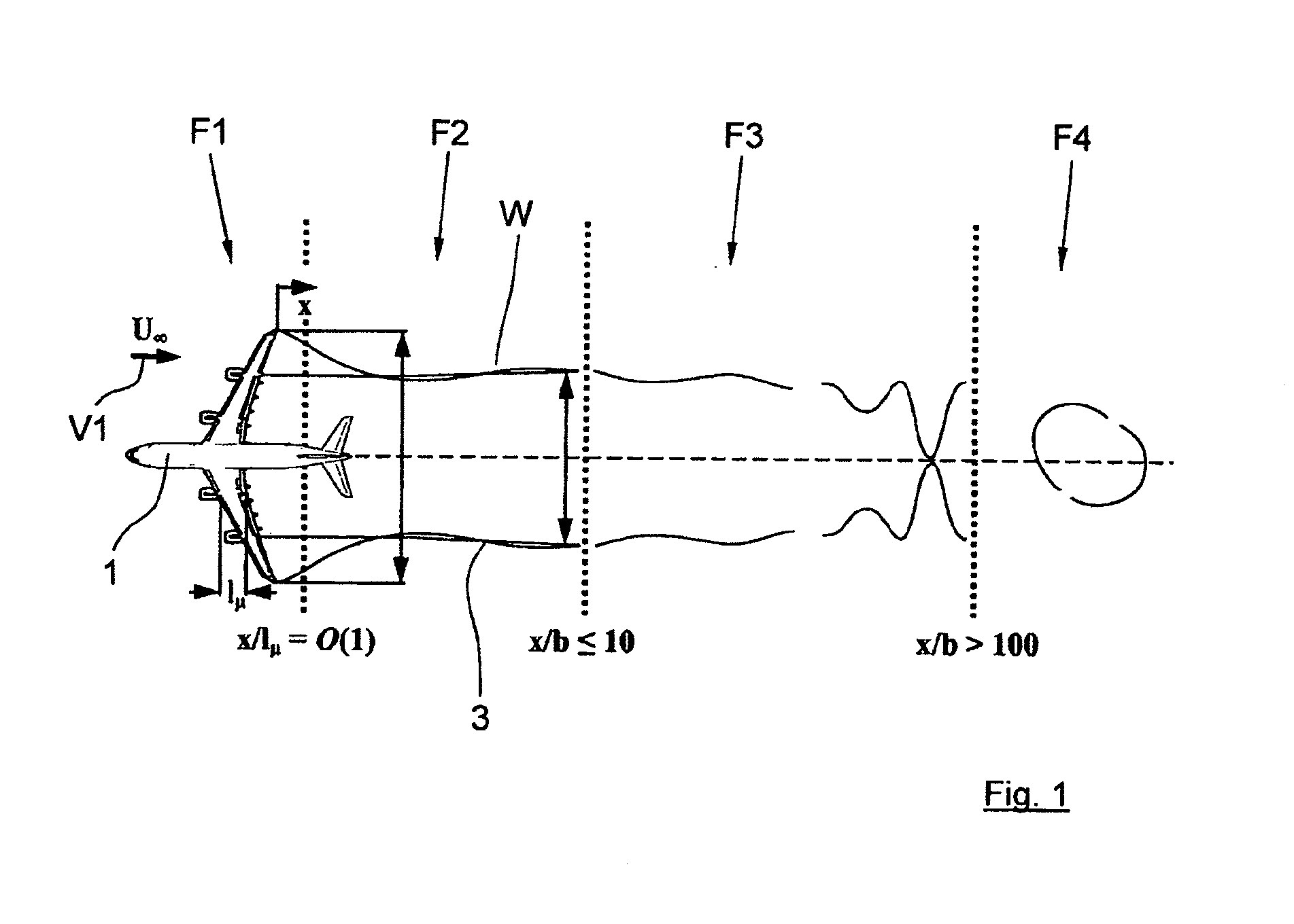
[0068]The invention influences the wake eddy system of aircraft, in particular larger aircraft, such as jumbo jets or transport aircraft. In particular, the eddy trail induced separation distances are reduced as a result, so that aircraft can takeoff and land at shorter time intervals. FIG. 1 shows a diagrammatic view of an aircraft 1 with ambient air flowing around it at a speed of v1, generating eddies or eddy trails W. Relative to the eddy formed by the primary wing, an expanded near field or expanded near range F2 extends behind a near field or near range F1 that extends a relatively short way behind the primary wing 2 of the aircraft 1, and is the site of an eddy formation and eddy unfurling process. Instabilities develop in a far field or far range F3 lying behind the latter in relation to the flying direction as the result of overlapping disturbances, e.g., atmospheric turbulence. The eddy W decays in a range F4: The created eddy swirls come into contact, break up and form ed...


PUM


Abstract

An aerodynamic element attachable to a primary wing to extend in a longitudinal direction at an angle to a spanwise direction of the primary wing. The aerodynamic element includes a downstream end having at least two flow flaps arranged next to each other and oriented in the longitudinal direction of the aerodynamic element.

Description

CROSS-REFERENCE TO RELATED APPLICATIONS[0001]The present application is a U.S. National Stage of International Patent Application No. PCT / EP2007 / 008038 filed Sep. 15, 2007 which published as WO 2008 / 031620 on Mar. 20, 2008, and claims priority of German Patent Application No. 10 2006 043 469.2 filed Sep. 15, 2006.BACKGROUND OF THE INVENTION[0002]1. Field of the Invention[0003]The invention relates to an aerodynamic element for attachment to a wing, or a wing with a primary wing. At least one such additional aerodynamic element can also be utilized. A computer with an actuator-activation module is also provided, as well as a computer program for implementation in a computer with an actuator-activation module. A method for influencing command signals for an actuator system is also provided, as well as combinations of such a computer with an actuator-activation module, a wing and at least one actuator for purposes of destabilizing wake eddy systems, which can take place utilizing, in p...

Claims


Application Information

Patent Timeline
IPC IPC(8): B64C23/06G05D1/08
CPCB64C13/16Y02T50/164B64C23/065B64C23/076Y02T50/10
Inventor BREITSAMTER, CHRISTIANALLEN, ALEXANDER
Owner TECH UNIV MUNCHEN
Why Eureka
Try Eureka