Supercharge Your Innovation With Domain-Expert AI Agents!

Pointing device

a pointing device and pointer technology, applied in the field of pointing devices, can solve the problems of difficulty in moving the expert cannot immediately move the cursor to a target position, and the expert may be often dissatisfied

Active Publication Date: 2010-01-14
ALPS ALPINE CO LTD
View PDF6 Cites 1 Cited by
  • Summary
  • Abstract
  • Description
  • Claims
  • Application Information

AI Technical Summary

Benefits of technology

The patent describes a pointing device that improves operability by reflecting an operating force in a perpendicular direction in the cursor moving speed in an X-Y plane direction. The device includes an operation body that operates a cursor moving on a display screen, a detection unit that detects the operating force, a cursor control unit that generates cursor movement data, a communication control unit that outputs the data, and a central control unit that controls the operation of the units. The cursor control unit includes a cursor-speed determining unit and a recording unit. The cursor-speed determining unit changes a reference function using the operating force in the perpendicular direction and determines the cursor moving speed in the X-Y plane direction accordingly. This improves the operability of the pointing device and makes it easier for users to move the cursor. The pointing device can be provided as firmware or driver software for various devices such as mobile phones or computers.

Problems solved by technology

In addition, since it is typical that a beginner feels that the cursor moving speed is high during the operation, there is a problem in that it is very difficult to move a cursor to a target position.
However, a cursor moving speed, which is felt to be high by a beginner, may be felt to be low by an expert, and the expert cannot instantly move the cursor to a target position.
For this reason, an expert may be often dissatisfied.
Since respective operators have different habits as described above, there has been a limit on obtaining operability that could satisfy all operators.

Method used


Image

  • Pointing device
  • Pointing device
  • Pointing device

Examples


Embodiment Construction

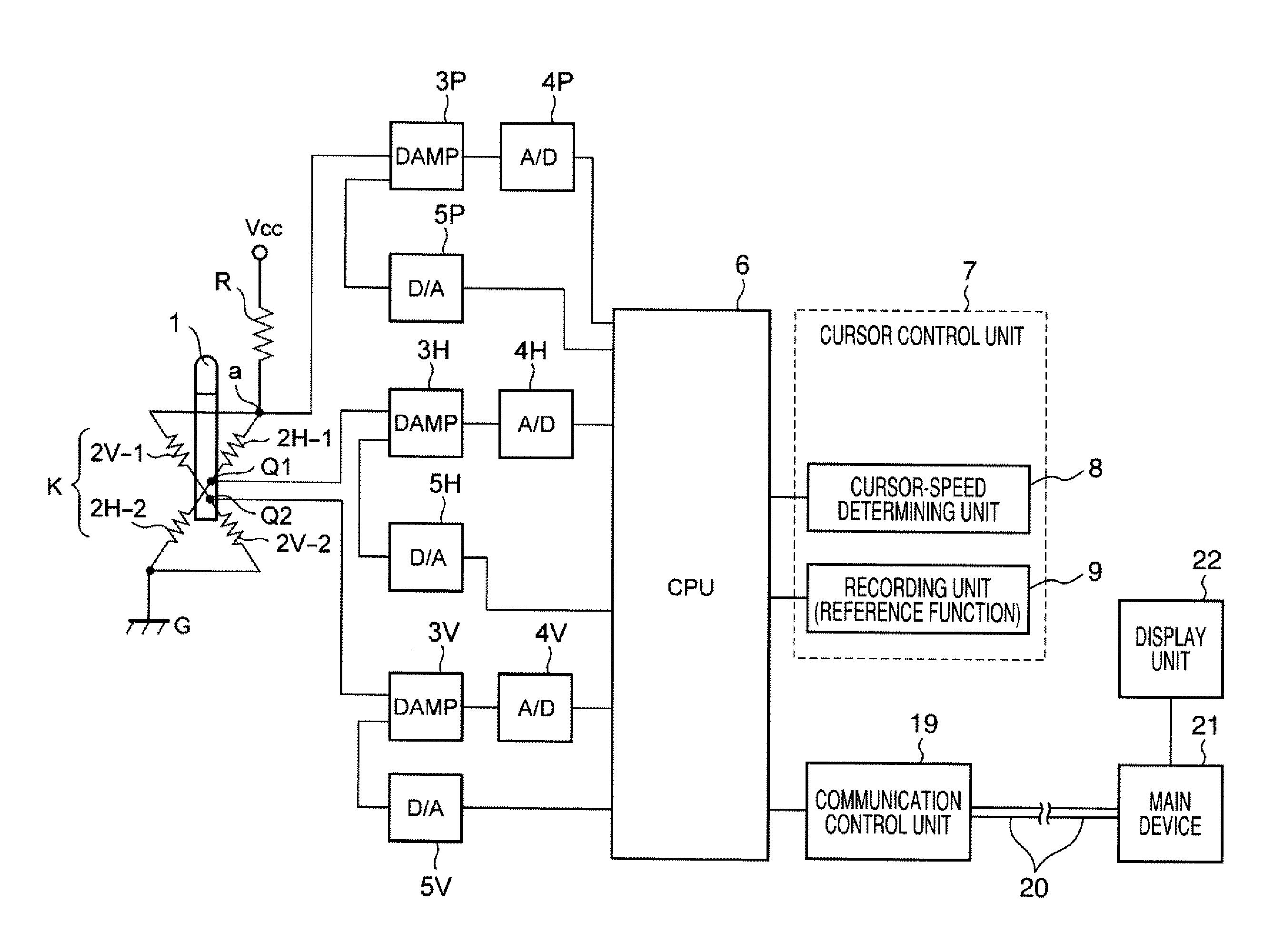
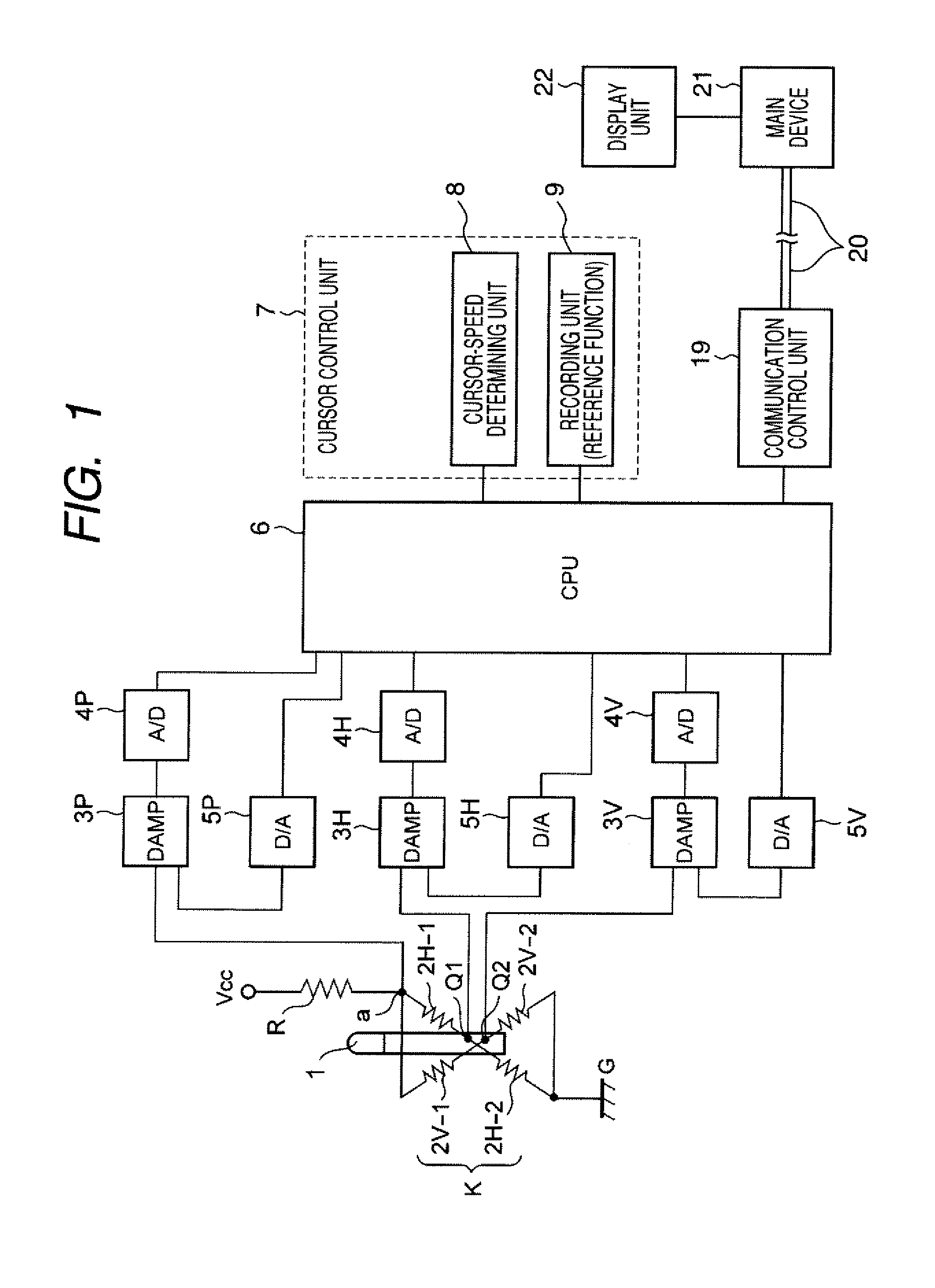
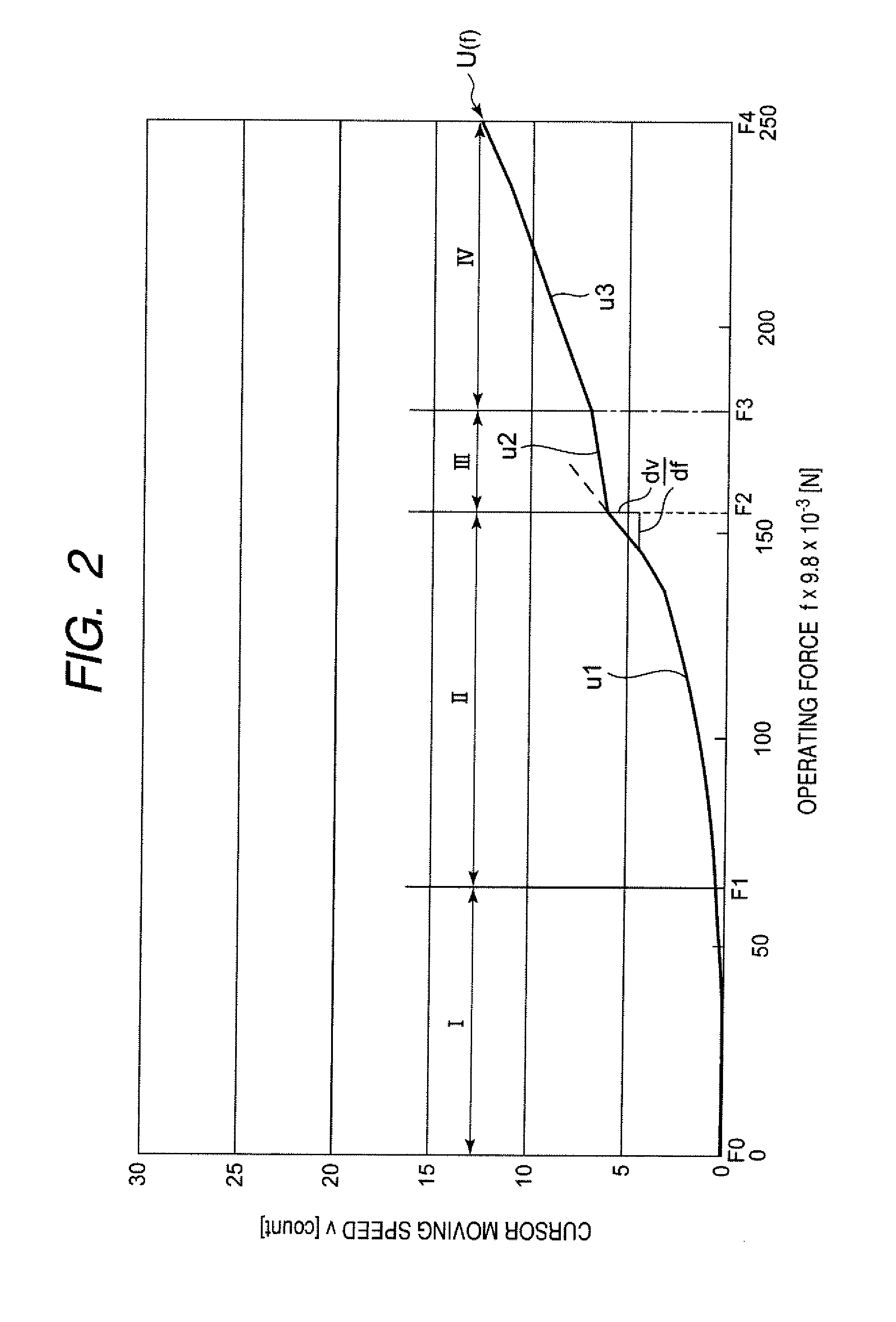
[0025]The following description is intended to convey a thorough understanding of the embodiments described by providing a number of specific embodiments and details involving pointing devices. It should be appreciated, however, that the present invention is not limited to these specific embodiments and details, which are exemplary only. It is further understood that one possessing ordinary skill in the art, in light of known systems and methods, would appreciate the use of the invention for its intended purposes and benefits in any number of alternative embodiments, depending on specific design and other needs. FIG. 1 is a block diagram of a pointing device, which includes a stick-type operation unit, according to various embodiments. FIG. 2 is a graph illustrating a reference function that defines a relationship between an operating force and cursor moving speed. Meanwhile, in FIG. 2, the horizontal axis represents an operating force f that is applied to the stick-type operation u...


PUM


Abstract

A pointing device includes an operation body that operates a cursor moving on a display screen, a detection unit that detects an operating force applied to the operation body, a cursor control unit that generates cursor movement data according to the operating force, a communication control unit that outputs the cursor movement data to the outside, and a central control unit that controls the operation of the units. The cursor control unit includes a cursor-speed determining unit and a recording unit. The cursor-speed determining unit determines cursor moving speed in an X-Y plane direction by a predetermined reference function from an operating force in an X-Y plane direction and an operating force in a perpendicular z axis direction perpendicular to the X-Y plane direction that are detected by the detection unit. The recording unit stores the reference function. The cursor-speed determining unit changes the reference function in accordance with the magnitude of the operating force in the perpendicular Z axis direction, and determines the cursor moving speed in the X-Y plane direction by the changed function.

Description

CROSS REFERENCE TO RELATED [0001]The present invention contains subject matter related to and claims the benefit of Japanese Patent Application No. 2008-179660 filed in the Japanese Patent Office on Jul. 10, 2008, the entire contents of which is incorporated herein by reference.BACKGROUND OF THE DISCLOSURE[0002]1. Technical Field[0003]The present invention relates to a pointing device that controls the motion of a cursor moving on a screen, and more particularly, to a pointing device that changes the cursor moving speed in accordance with an operating force.[0004]2. Related Art[0005]When an operator operates a pointing device, the moving distance, the direction, and the speed of a cursor are generally adjusted by the magnitude of a force applied to an operation body of the pointing device.[0006]For example, Japanese Unexamined Patent Application Publication No. 9-34644 discloses a pointing device that changes a function to be used for each magnitude range of a force applied to the p...

Claims


Application Information

Patent Timeline
Patent Type & Authority Applications(United States)
IPC IPC(8): G09G5/08G06F3/0338G06F3/038
CPCG06F3/038G06F3/03545
Inventor OHSHITA, KAZUHITO
Owner ALPS ALPINE CO LTD
Features
  • R&D
  • Intellectual Property
  • Life Sciences
  • Materials
  • Tech Scout
  • Unparalleled Data Quality
  • Higher Quality Content
  • 60% Fewer Hallucinations
Learn More