Avionics equipment carrier system with quick-mount housing and quick-mount modules

a carrier system and aircraft technology, applied in the direction of electric apparatus casings/cabinets/drawers, instruments, transportation and packaging, etc., can solve the problems of inability to quickly exchange the individual components of an afis, affecting the efficiency of the system, and requiring a considerable amount of time for deinstallation,

Active Publication Date: 2010-01-14
AIRBUS OPERATIONS GMBH
View PDF10 Cites 63 Cited by
  • Summary
  • Abstract
  • Description
  • Claims
  • Application Information

AI Technical Summary

Benefits of technology

[0015]In order to combine several equipment groups, which are accommodated in different avionics equipment carrier system housings, they can advantageou

Problems solved by technology

At present, equipment carriers exist which make it possible to quickly exchange individual components in the case of a defect or in the case of a desired retrofit (due to this ability also referred to as line replaceable units, LRUs), but which as an entity do not offer this ability.
Thus, the Rockwell Collins ISC-2100 (information services cabinet, see also http://www.rockwellcollins.com/products/cs/at/page982.html) is not designed as an LRU, i.e. it cannot quickly be deinstalled from an avionics rack; instead, deinstallation requires a degree of effort and above all a considerable amount of time.
However, the dimensions of the surrounding housing of the ISC-2100 do not comply with any ARINC standards, so that particularly for the ISC-2100 a specially designed accommodation rack in the aircraft becomes necessary, in which rack the housing can be firmly installed.
Quick exchange of the individual components of an AFIS is thus not possible.
The network server system SAGEM A380 NSS (see also http://www.sagem-ds.com/eng/bds_navio—200.htm) while comprising an LRU housing, which does not however conform to ARINC, does not make it possible either to quickly exchange integratable components; such exchange requires dismantling of the entire

Method used


Image

  • Avionics equipment carrier system with quick-mount housing and quick-mount modules
  • Avionics equipment carrier system with quick-mount housing and quick-mount modules
  • Avionics equipment carrier system with quick-mount housing and quick-mount modules

Examples


Embodiment Construction

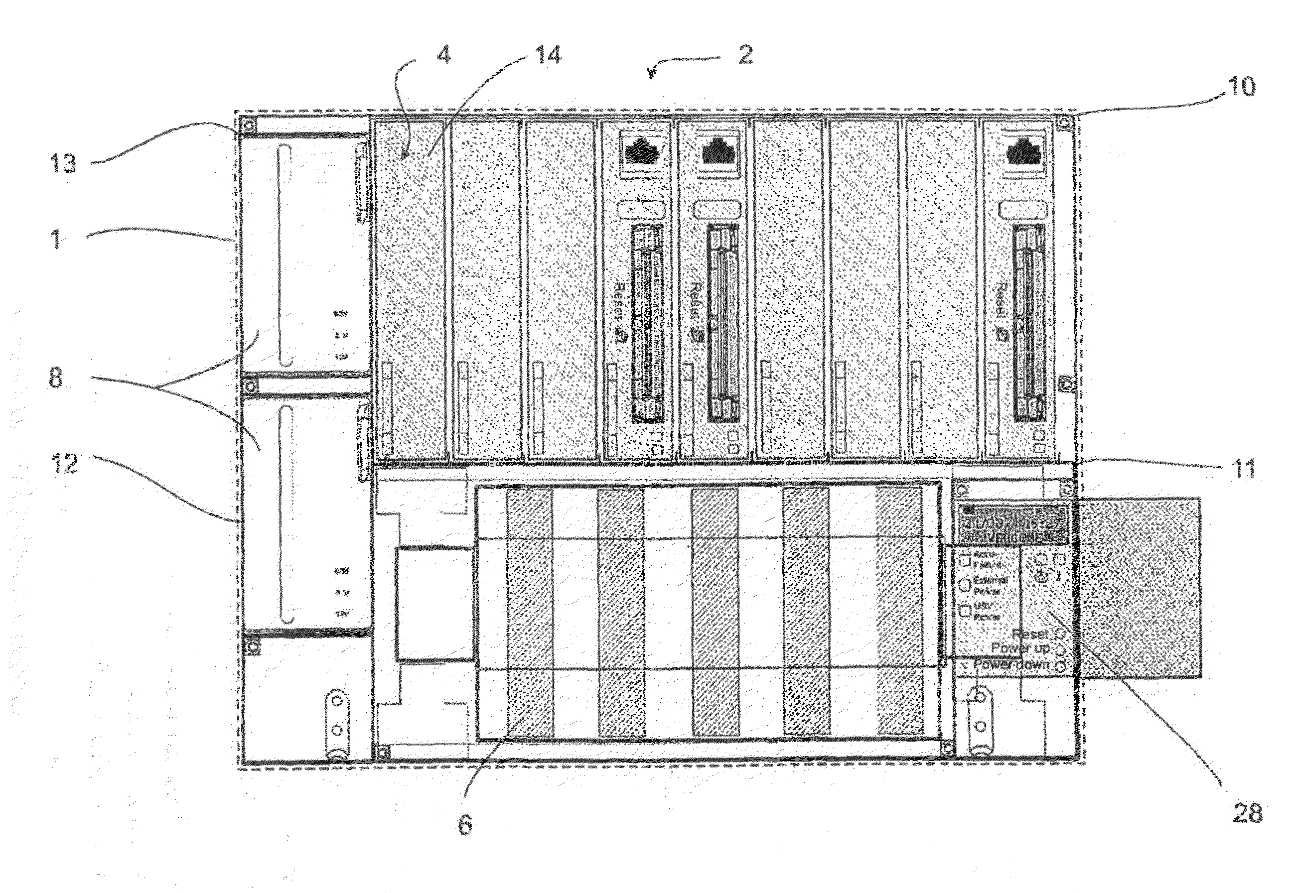
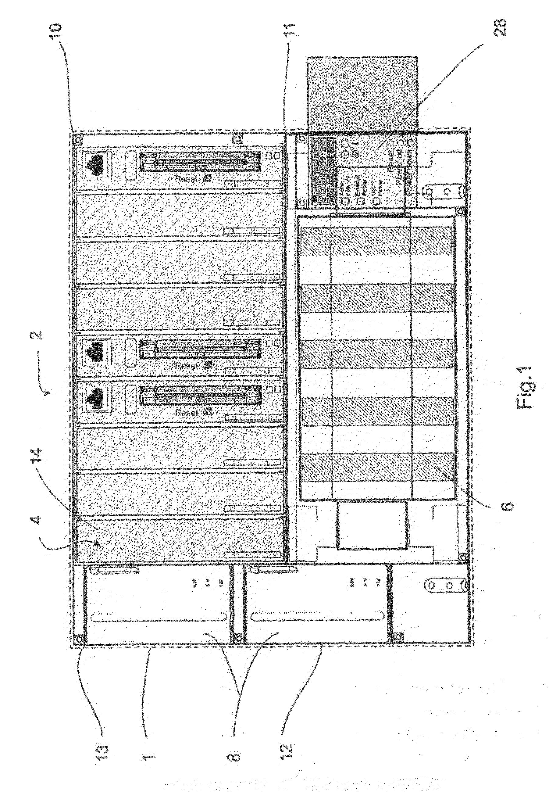
[0022]FIG. 1 shows the front view of an equipped avionics equipment carrier system 2, inserted in an avionics rack 1, with slide-in modules 4, 6 and 8 that are inserted in racks 10, 11 and 13 located in the housing 12. The rack 10 is located above the rack 11 and accommodates the slide-in modules 4. In the lower rack 11 the slide-in modules 6 are arranged. In a further rack 13, which is adjacent to the left-hand side of the previously mentioned modules, two slide-in modules 8 are arranged, one on top of the other.

[0023]In order to facilitate the retrofitting of additional devices or the modernisation of a module rack (hereinafter referred to as an avionics rack), the housing 12 of the avionics equipment carrier system 2 according to the invention comprises dimensions that comply with a common standard in relation to widely used avionics racks, such as, for example, the ARINC 600 standard. Accordingly it is possible to insert the housing 12 in a free region of an avionics rack where ...


PUM


Abstract

An avionics equipment carrier system for slide-in modules with data processing, data transmitting, data storage or data displaying devices, such as for example electronics printed circuit boards, network components, storage devices, display devices and the like, or power supply devices, includes a housing, at least one module rack for accommodating the slide-in modules and at least one backplane board with Ethernet connection architecture. When the dimensions of the housing comply with ARINC standards, and the housing is arranged for installation in an avionics module rack as a quick-mount housing, and any desired circuit boards of a specific standard format can be used in the slide-in modules which are designed as quick-mount modules.

Description

REFERENCE TO RELATED APPLICATIONS[0001]This application claims the benefit of the filing date of German Patent Application No. 10 2005 044 712.0 filed on Sep. 19, 2005 and of U.S. Provisional Patent Application No. 60 / 718,672 filed Sep. 20, 2005, the disclosure of which applications is hereby incorporated herein by reference.FIELD OF THE INVENTION[0002]The present invention relates to an avionics equipment carrier system for slide-in modules with data processing, data transmitting, data storage or data displaying devices, such as for example electronics printed circuit boards, network components, storage devices, display devices and the like, or power supply devices, comprising a housing, at least one module rack for accommodating the slide-in modules and at least one backplane board with Ethernet connection architecture.TECHNOLOGICAL BACKGROUND[0003]Avionics devices in aircraft are generally integrated in an avionics rack located in the cockpit or in close proximity to the cockpit....

Claims


Application Information

Patent Timeline
IPC IPC(8): H05K7/14
CPCH05K7/1424H05K7/1412
Inventor OSTERNACK, STEFANSCHALKE, OLIVERREHMEIER, SVENBRADTKE, JORG
Owner AIRBUS OPERATIONS GMBH
Why Eureka
Try Eureka