Electrical connector assembly tool

Inactive Publication Date: 2010-01-21
TE CONNECTIVITY CORP +1
View PDF11 Cites 17 Cited by
  • Summary
  • Abstract
  • Description
  • Claims
  • Application Information

AI Technical Summary

Benefits of technology

[0015]An advantage of the present invention is the increased ability to avoid electrical shock when installing specific electrical connectors.
[0016]Another advantage of the present invention is the ability to prevent a connector from spinning around a bolt.
[0017]Yet another advantage of the present invention is the providing of compliance.
[0018]Still yet another advantage of the present invention is the ability to limit movement to substantially two-dime

Problems solved by technology

Bolt-on connectors have been widely accepted in the industry primarily due to their ease of installation, but such connectors are not without disadvantages.
Such compression connectors are generally available at a lower cost than bolt-on connectors, but are more difficult to install.
Such connectors tend to be more expensive than either bolt-on or compression connectors, but are generally believed to provide superior performance over bolt-on and compression connectors.
The style of electrical connector dis

Method used


Image

  • Electrical connector assembly tool
  • Electrical connector assembly tool
  • Electrical connector assembly tool

Examples


Example

[0029]The present invention now will be described more fully hereinafter with reference to the accompanying drawings, in which a preferred embodiment of the invention is shown. This invention may, however, be embodied in many different forms and should not be construed as limited to the embodiments set forth herein; rather, these embodiments are provided so that this disclosure will be thorough and complete and will fully convey the scope of the invention to those skilled in the art.

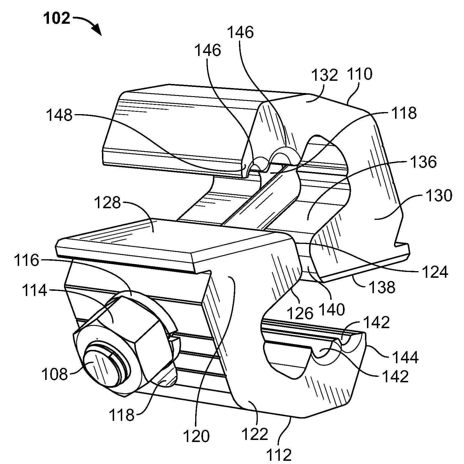
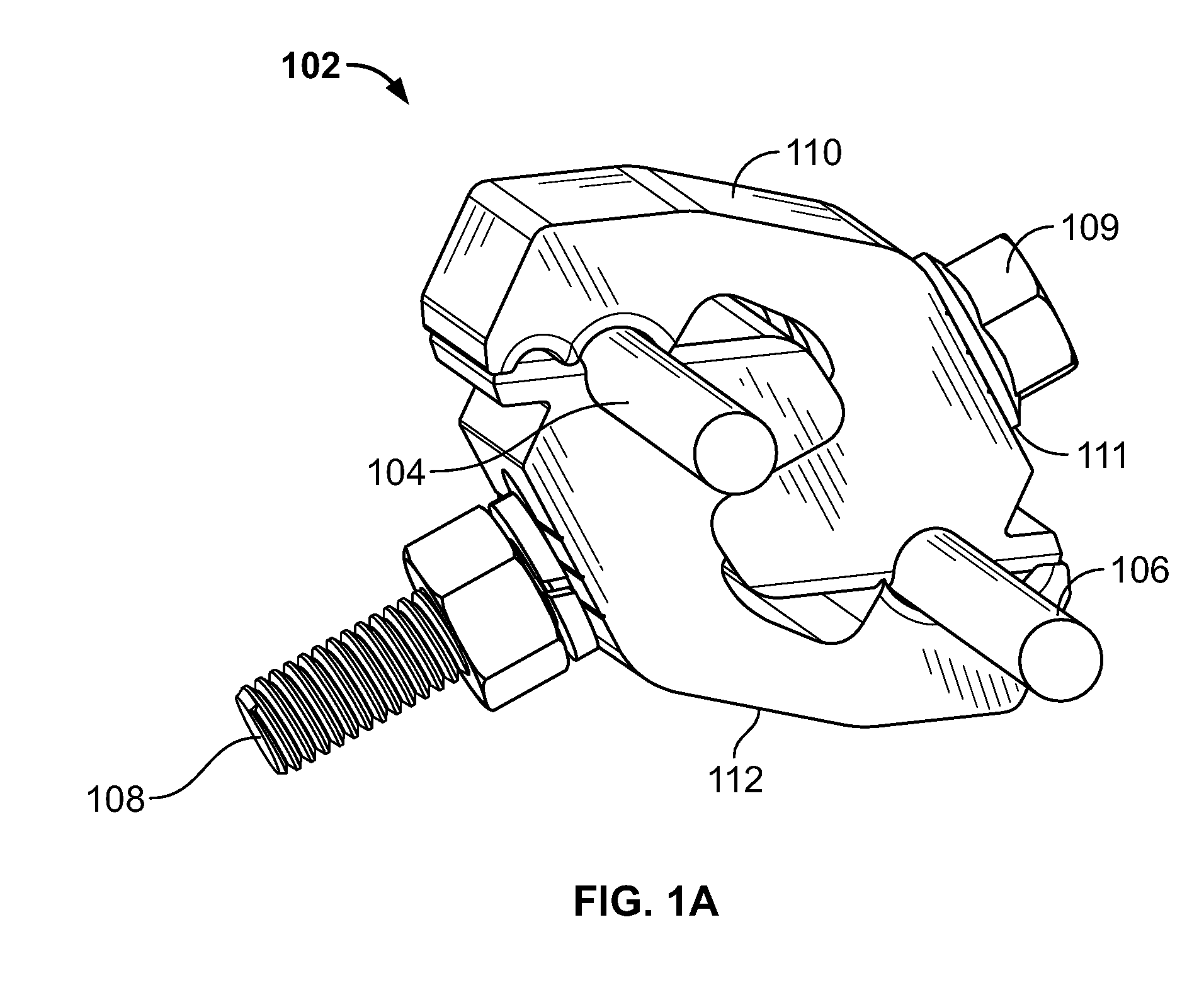
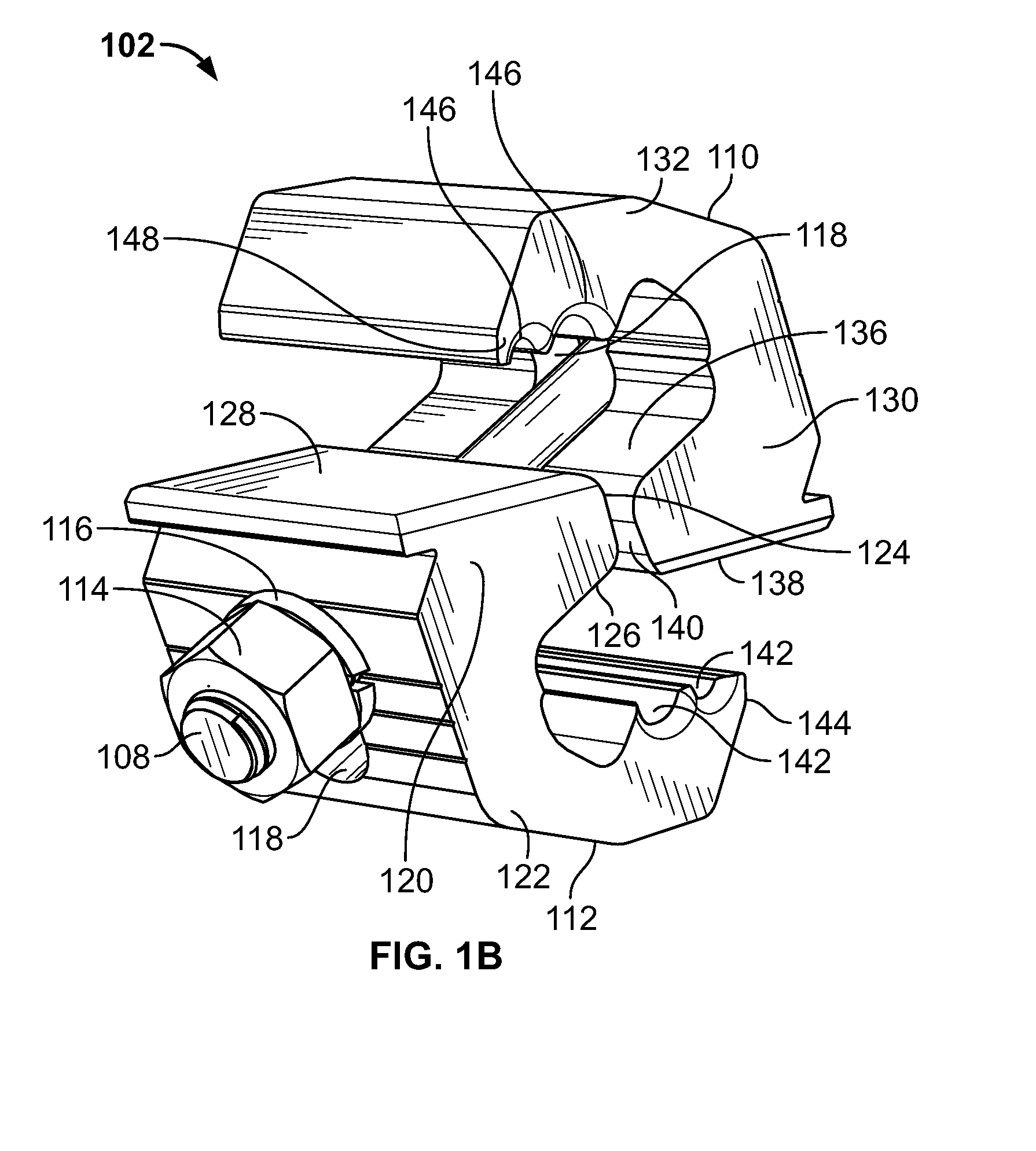
[0030]FIG. 1A illustrates an embodiment of an electrical connector 102 in a mated position. As illustrated, connector 102 includes two substantially similar portions configured to be used as an electrical connector for high voltage utility conductors. In some embodiments, the portions may be identical. In other embodiments, the portions may be geometrically dissimilar. Connector 102 is configured to electrically connect a main power conductor 104 and a tap conductor 106. It will be apparent that the term...


PUM

PropertyMeasurementUnit
Forceaaaaaaaaaa
Electrical conductoraaaaaaaaaa
Dimensionaaaaaaaaaa

Abstract

An electrical connector tool assembly is disclosed. The tool assembly includes a conductor tool and a connector tool connected to and cooperable with the conductor tool. The tool assembly can be used in connecting a first conductor to a second conductor with an electrical connector. The tool assembly is adjustably arranged and disposed to receive and removably retain a first conductive member of an electrical connector in the connector tool and is further arranged and disposed to both to hold the second conductor in place relative to a second conductive member of the electrical connector and to prevent rotation of the second conductive member with respect to the first conductive member.

Description

FIELD OF THE INVENTION[0001]The present disclosure relates generally to tools for installing and removing electrical connectors. More specifically, the present disclosure relates to a tool assembly as used in the utility industry for the prevention of shock to utility workers.BACKGROUND OF THE INVENTION[0002]Electrical utility firms such as those constructing, operating or maintaining overhead and / or underground power distribution networks utilize connectors to tap main power transmission conductors and feed electrical power to distribution line conductors, sometimes referred to as tap conductors. The main power line conductors and the tap conductors are typically high voltage conductors that are relatively large in diameter and the main power line conductor may be differently sized from the tap conductor. As a result, specially designed connector components are often needed to adequately connect tap conductors to main power line conductors. Generally, three types of connectors are ...

Claims


Application Information

Patent Timeline
IPC IPC(8): B23P19/00H01R43/042
CPCH01R4/5091H01R43/00Y10T29/53274Y10T29/53243Y10T29/53257Y10T29/53217Y10T29/53222Y10T29/53226
Inventor COPPER, CHARLES DUDLEYJOHNSON, BARRY JAMESLADIN, DMITRY
Owner TE CONNECTIVITY CORP
Why Eureka
Try Eureka