Coffee grinder-dispenser with cooling fans

a technology of coffee grinder and fan, which is applied in the field of coffee grinder, can solve the problems of inability to completely rely on fans, adverse effects of heat rising from electric motors on the organoleptic characteristics of ground coffee, and inability to efficiently and effectively dissipate heat, etc., and achieve excellent taste and aroma, excellent effect of heat dissipation

Inactive Publication Date: 2010-01-21
MAZZER LUIGI
View PDF9 Cites 35 Cited by
  • Summary
  • Abstract
  • Description
  • Claims
  • Application Information

AI Technical Summary

Benefits of technology

[0006]Consequently, with the disadvantages of known coffee grinder-dispensers clearly in mind, the invention is directed to a cooling system, relying upon a pair of strategically positioned fans, that will efficiently and effectively dissipate the heat within the base of the coffee grinder-dispenser, thereby maintaining the desired organoleptic characteristics of the ground coffee, such as excellent taste and wonderful aroma.
[0007]An object of the invention is to eliminate this drawback by providing a grinder-dispenser, with cooperating cooling fans, which enable the coffee to maintain its organoleptic characteristics.

Problems solved by technology

The heat from the relatively large electric motor is not readily dissipated within the confines of the base, and the heat rising from the electric motor adversely impacts upon the organoleptic characteristics of the ground coffee, such as taste and smell.
The Mazzer patent does not recognize this problem, and makes no effort to overcome same.
While the cooling fan on the vertical shaft has alleviated the heat build-up problem to some degree, the reliance upon such fan has not been completely successful, and, in some instances, has proven to be unreliable.
The heat from the electric motor continues to rise upwardly within the housing and negatively impact upon the ground coffee, after the grinding operation has been terminated.

Method used


Image

  • Coffee grinder-dispenser with cooling fans
  • Coffee grinder-dispenser with cooling fans

Examples


Embodiment Construction

DETAILED DESCRIPTION OF THE INVENTION

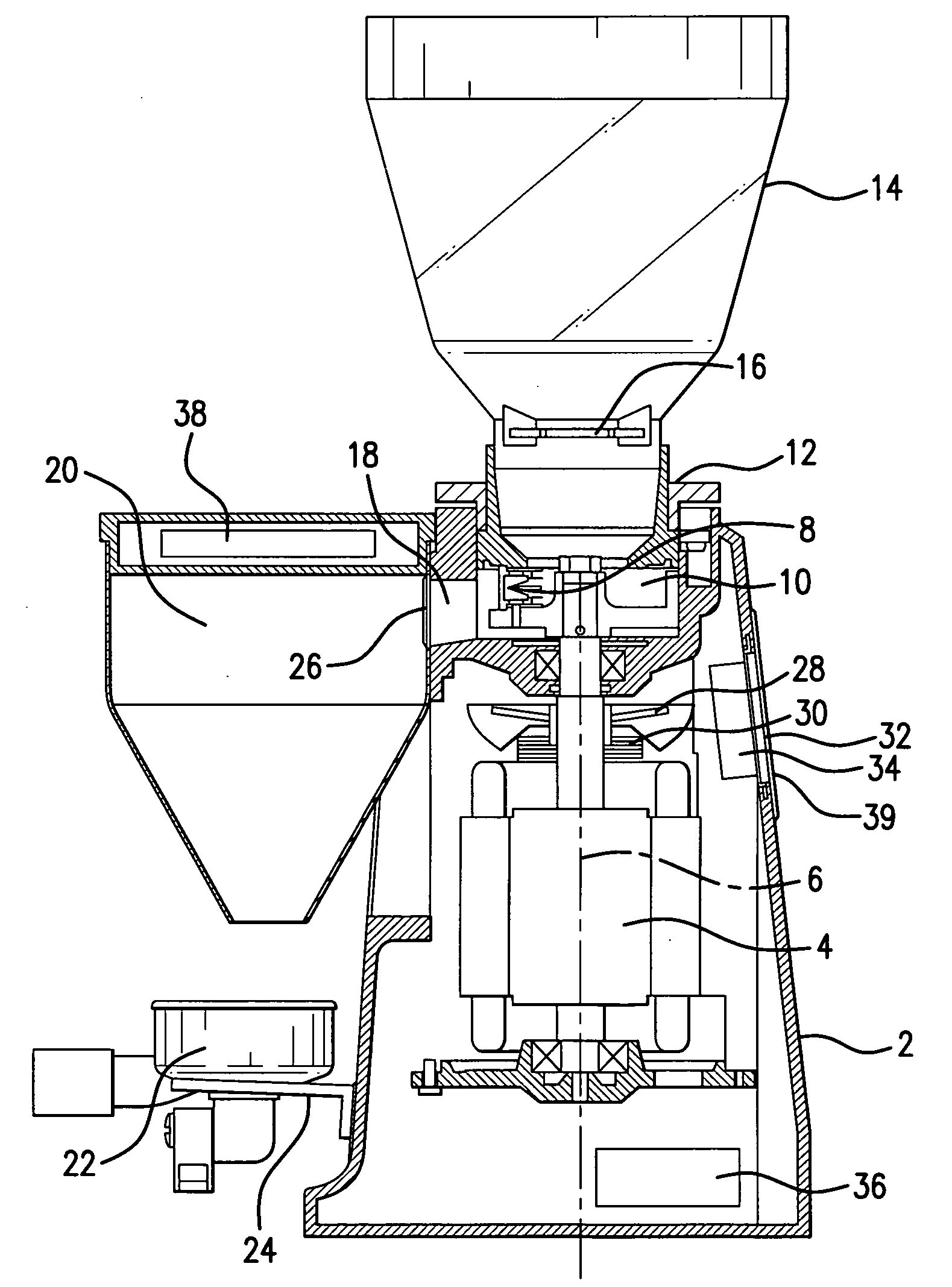
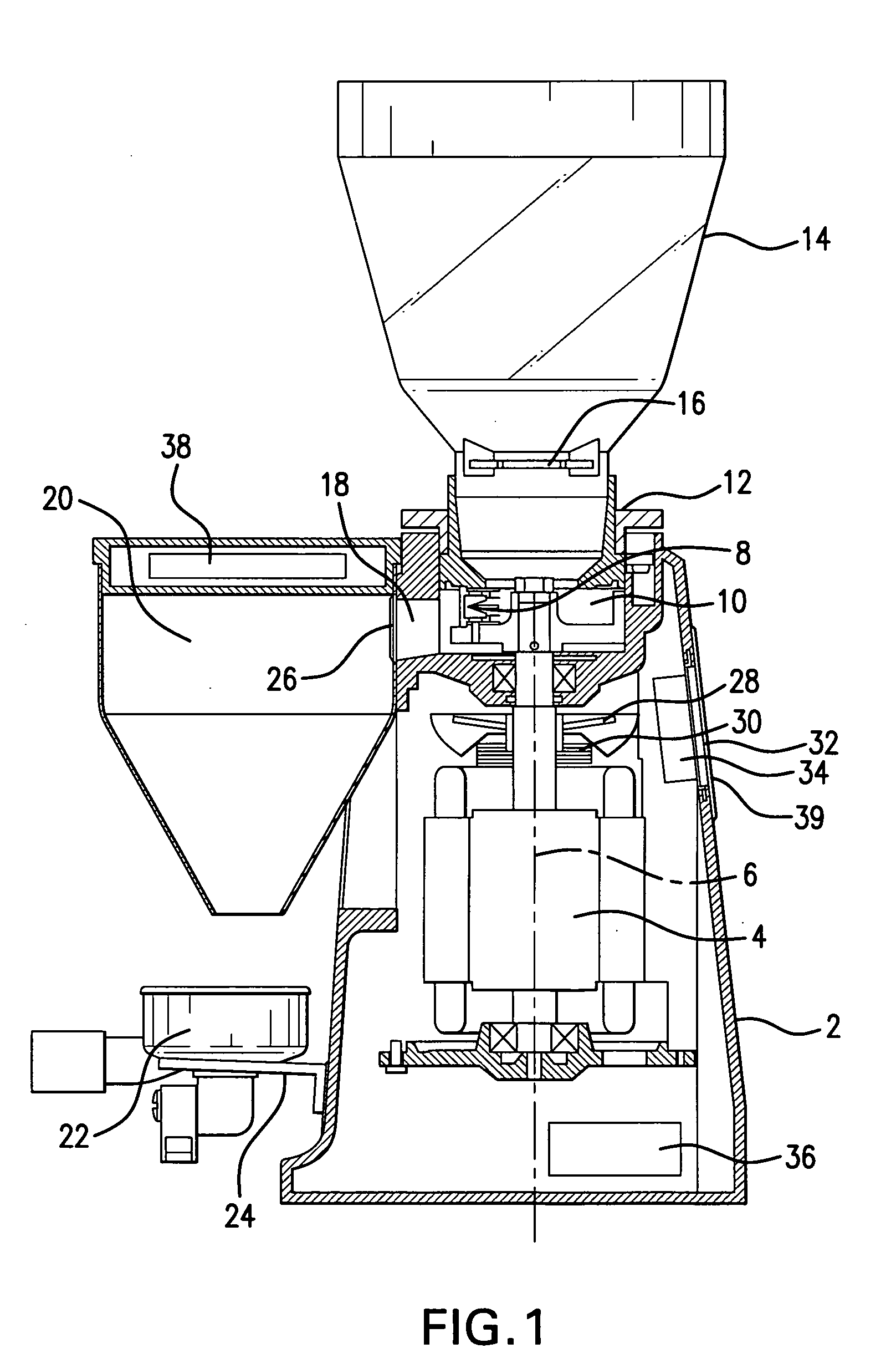
[0012]As can be seen from FIG. 1, the coffee grinder-dispenser of the invention comprises substantially a base 2 housing an electric motor 4. The output shaft 6 of the motor is rigidly connected to a grinder, indicated overall by 8, and located within a grinding chamber 10.

[0013]A fitting 12 is located at the upper end of grinding chamber 10, and a transparent plastic bell-shaped vessel 14 is inserted into fitting 12. A closure gate 16 regulates the volume of the coffee beans, retained in vessel 12, which are admitted into chamber 10.

[0014]The grinding chamber 10 is also provided with a conduit 18, which communicate with funnel 20 for conveying the ground coffee from chamber 10 to filter holder 22 supported by a suitable support 24 on the lower face of housing 2.

[0015]A metal grid 26, of stainless steel, is applied to the funnel entry facing the conduit 18 to reduce the speed at which the coffee is forced into the funnel. Consequently, the ground...


PUM


Abstract

A coffee grinder-dispenser comprising a base housing an electric motor, with a vertically extending rotatable shaft which is connected to a grinder located in a grinding chamber. A vessel located above the grinding chamber receives coffee beans to be ground. A closure plate allows the coffee beans to enter the grinding chamber. A conduit allows the coffee, after grinding, to be delivered to a funnel; the ground coffee passes downwardly through the funnel into a filter holder. One cooling fan faces the grinding chamber, is activated by a keypad on the funnel, and delivers air transversely across the interior of the housing. A second cooling fan is located on the vertical shaft of the electric motor. The fans are operated by a controller, located within the housing, and provide sufficient cooling air to the grinding chamber to maintain the desired qualities of taste and aroma in the ground coffee.

Description

FIELD OF THE INVENTION [0001]The present invention relates generally to a coffee grinder-dispenser, and more particularly to two cooling fans for dissipating heat build-up within the housing of the coffee grinder-dispenser that may adversely influence the taste and smell of the ground coffee.BACKGROUND OF THE INVENTION [0002]Coffee grinder-dispensers comprising a base housing an electric motor, with a vertically extending output shaft, connected to a grinder located within a grinding chamber, are well known. A transparent bell-shaped vessel, located a the upper end of the base, receives the coffee beans to be ground, and a closure gate regulates the flow of beans into the grinding chamber. After grinding, the ground coffee, or powder, passes through a conduit, n the housing, into the upper end of a funnel secured to the housing. A stainless steel grid is located in the conduit to reduce the velocity of the coffee powder, so that it flows smoothly through the funnel and is discharged...

Claims


Application Information

Patent Timeline
Patent Type & Authority Applications(United States)
IPC IPC(8): A47J42/00B02C23/00F28D15/00F28F13/12
CPCA47J42/54A47J31/52A47J31/401A47J31/0663A47J42/40
Inventor MAZZER, GIOVANNI
Owner MAZZER LUIGI
Why Eureka
Try Eureka